
Roller skate

a technology of roller skates and skates, which is applied in the field of roller skates, can solve the problems that the roller skate design of the type discussed in the background section is not suited to avoid, and achieve the effects of reducing physical strain on users, improving travel safety, and improving comfort during travel

Inactive Publication Date: 2010-07-20
ABEL HELMUT
View PDF34 Cites 5 Cited by
  • Summary
  • Abstract
  • Description
  • Claims
  • Application Information

AI Technical Summary

Benefits of technology

[0015]The present invention has the basic problem of designing these known inliners in such a manner that the physical strain on the users is reduced and that better comfort during travel and in particular considerably more travel safety is offered so that these roller skates are better suited even for less experienced and less talented users.
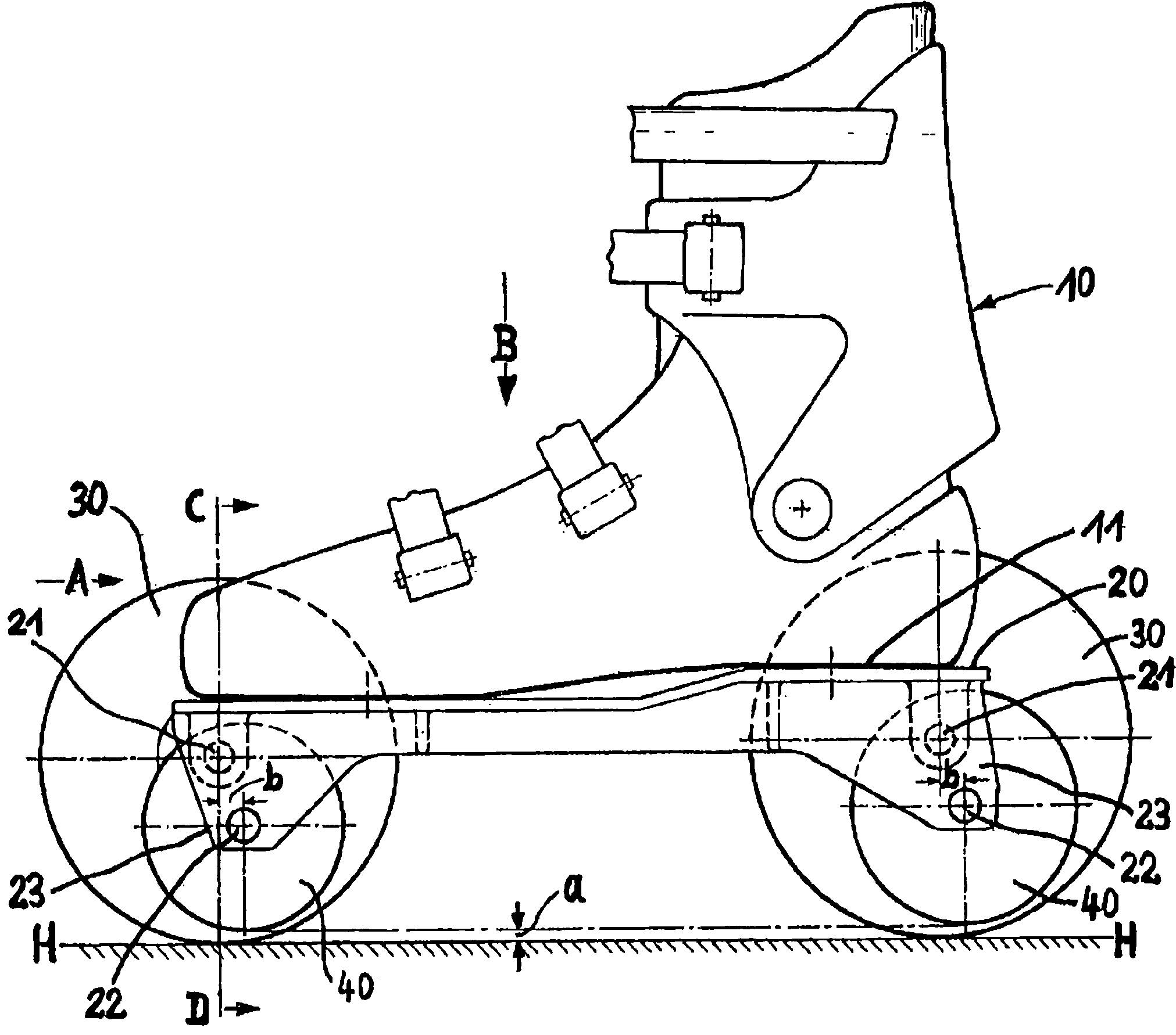
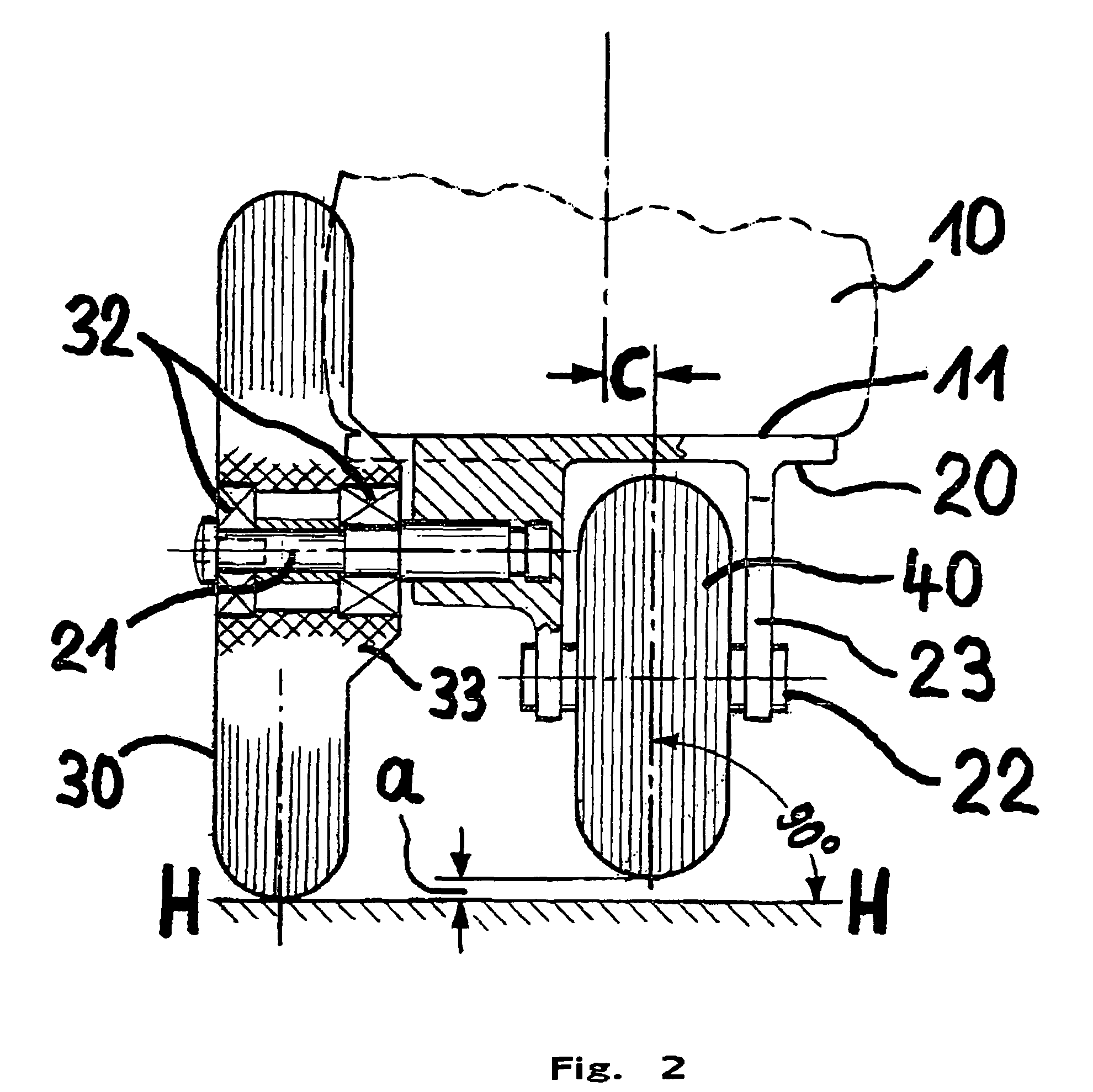
[0019]Instead of a laterally offset third roller adjacent to the inline rollers, outer rollers are arranged in the area of the outside of the shoe that extend upward over the sole of the boot and whose diameter is greater than the diameter of the inline rollers. The inline rollers are mounted on the frame in such a manner that their bearing surface is at a distance from the traveling surface in the case of a sole situated parallel to the traveling surface. When standing and during travel these outer rollers serve as support, which avoids the very unpleasant and strenuous lateral tilting movements whereas during pushing off exclusively the inline rollers make contact with the traveling surface.
[0020]The fact that the diameter of the outer rollers is greater than the diameter of the inline rollers facilitates traveling over hindrances in the road surface. In one embodiment, the axles of the outside rollers are located in the direction of travel in front of the axles of the inline rollers.
[0021]Other structures and their structural arrangements result in an improvement of the travel comfort.
[0023]It proved to be advantageous if the longitudinal axis of the inline rollers running in the direction of travel is inwardly offset relative to the parallel, central longitudinal axis of the boot sole. In this roller arrangement it is relatively simple for the users to go out of the four-roller position into the inline roller position.

Problems solved by technology

However, such a roller skate design of the type discussed in the background section is not suited for avoiding the above-describe disadvantages and solving the basic problem of the invention.

Method used


Image

  • Roller skate
  • Roller skate
  • Roller skate

Examples


Embodiment Construction

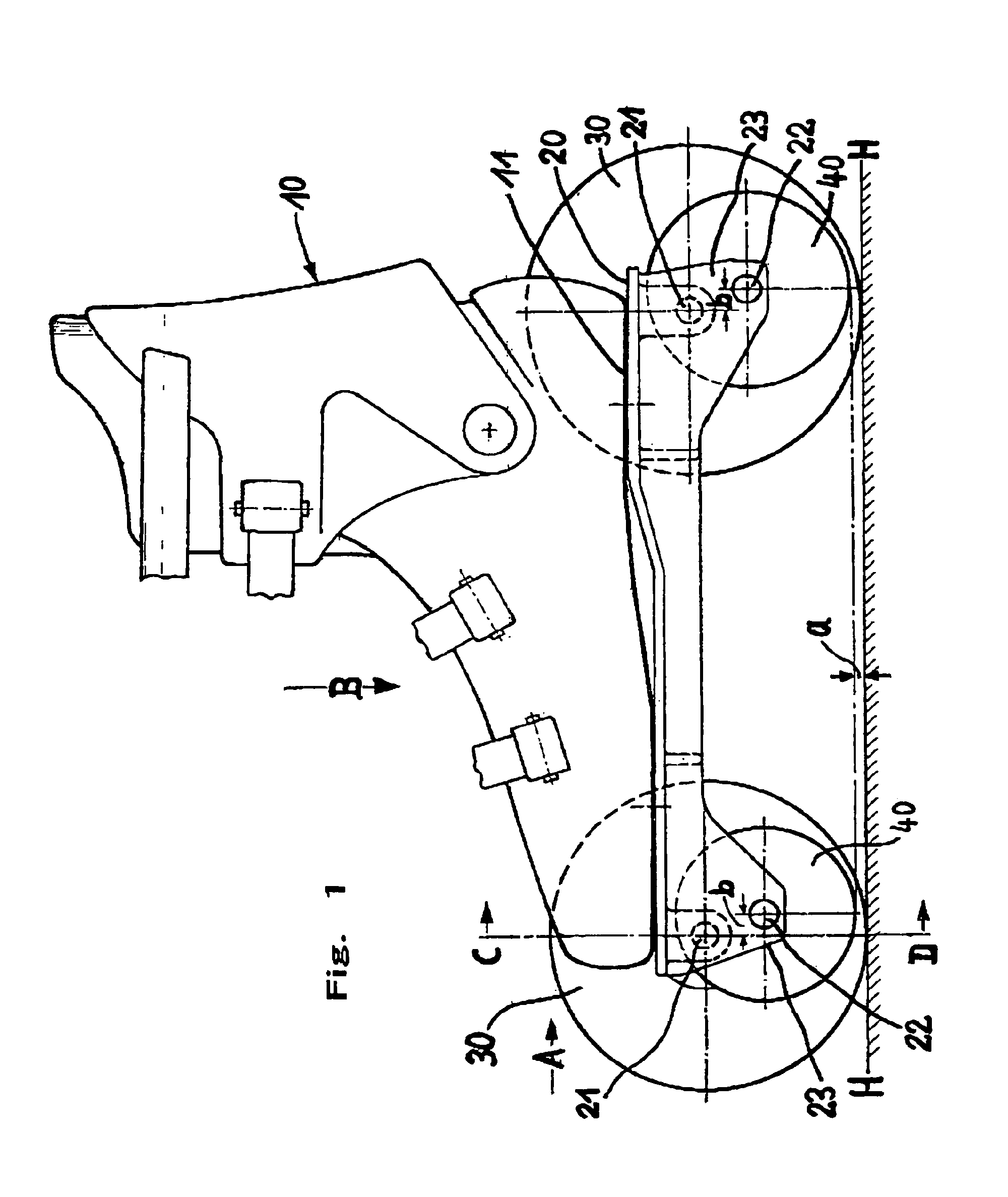
[0030]The invention is explained using the right roller skate of a pair of roller skates that is shown in different positions in FIGS. 1 to 5.

[0031]The roller skate consists substantially of a boot 10 on whose boot sole 11 the frame 20 with rollers 30 and 40 and serving as roller carrier element is fastened. The left roller skate (not shown) is constructed homologously. The larger rollers 30 are vertical to traveling surface H-H in this view. They are always located on the outside of the roller skate. The smaller rollers 40, that are located under boot 10 in a manner similar to inliners and therefore are designated in the following as inline rollers, maintain a distance a from the surface of traveling surface H-H.

[0032]In the exemplary embodiment shown in FIGS. 1 to 3 the back outer roller 30 is larger and wider that the front one.

[0033]The frame 20 consisting of injection-molding aluminum, injection-molding plastic or of welded steel comprises wheel forks 23 on its bottom that carr...


PUM


Abstract

The roller skate according to the invention is equipped with smaller inline rollers (40) arranged below the boot (10) and with outer, larger rollers (30), the upper parts of which protrude above the boot sole (11). This roller skate can be moved on four rollers (30) and (40) in the manner of a four-wheel roller skate, or, in certain phases, just on two inline rollers (40) in a similar manner to an inline skate.

Description

CROSS REFERENCE TO RELATED APPLICATION[0001]This application is a §371 National Phase of PCT / EP2006 / 011059, filed Nov. 17, 2006, the entirety of which is hereby incorporated by reference.BACKGROUND OF THE INVENTION[0002]The invention relates to a roller skate.[0003]Roller skates with four rollers arranged in pairs as well as with several rollers arranged in series, so-called inliners, and with mixed forms are known.[0004]The best-known ones are the four-wheel roller skates, that are generally equipped with four often relatively wide, usually cylindrical rollers with the same diameter. During travel such roller skates are placed on the road surface as a rule as horizontally as possible with all four rollers at the same time.[0005]The shoes of these four-wheel roller skates, that comprise front and back rollers that can be guided to a limited extent, are relatively low in the heel area so that the user can bend his legs to both sides in the area above the ankle. This makes it possible...

Claims


Application Information

Patent Timeline
IPC IPC(8): A63C17/02
CPCA63C17/004A63C17/006A63C17/0073A63C17/04A63C17/06
Inventor ABEL, HELMUTDEHAESELEER, OLIVIAABEL, CELINEABEL, DIANE
Owner ABEL HELMUT
Learn More