
Bowling ball with weight block

a weight block and bowling ball technology, applied in the field of bowling balls, can solve the problems of greater pin action and thus higher scores, and achieve the effects of improving bowling opportunities, greater pin action, and higher scores

Inactive Publication Date: 2010-07-13
LANE NO 1
View PDF5 Cites 2 Cited by
  • Summary
  • Abstract
  • Description
  • Claims
  • Application Information

AI Technical Summary

Benefits of technology

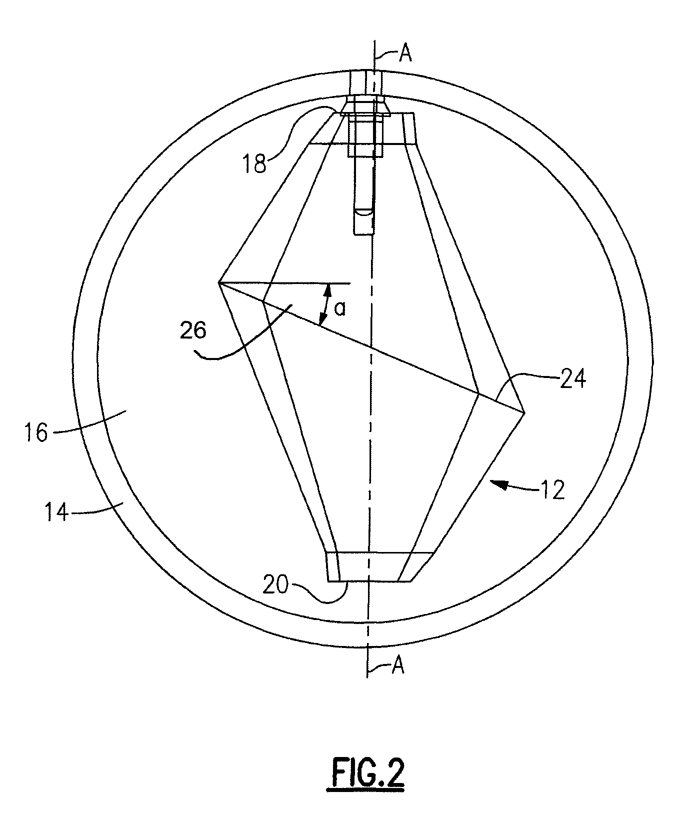
[0003]The weight block of the present invention is asymmetrical with respect to a central axis. That is, the weight block has a pair of ends through which the central axis of the block extends, and a medial portion which is offset or skewed with respect to the weight block axis. The block has an outer surface which has a maximum cross section in at least one plane intersected by the central axis which is intermediate of the two ends. This plane, i.e., the plane intersected by the central axis which is enclosed by a peripheral boundary defining the largest transverse cross section of the block is preferably in a flat plane which is not normal to the central axis. Rather, the medial plane is disposed at an angle, preferably of about 22.5° but in any case other than 90°, with respect to the central axis of the block. The plane of largest cross section is preferably about midway between the two ends of the weight block. The asymmetry of the weight block produces a spin and roll of the ball wherein it is incorporated which ultimately results in greater pin action and thus higher scores. The object of the invention is to provide a bowling ball incorporating a novel and improved weight block which improves the bowlers opportunities of achieving improved scores. Other objects will in part be obvious and will in part appear hereinafter.

Problems solved by technology

The asymmetry of the weight block produces a spin and roll of the ball wherein it is incorporated which ultimately results in greater pin action and thus higher scores.

Method used


Image

  • Bowling ball with weight block
  • Bowling ball with weight block
  • Bowling ball with weight block

Examples


Embodiment Construction

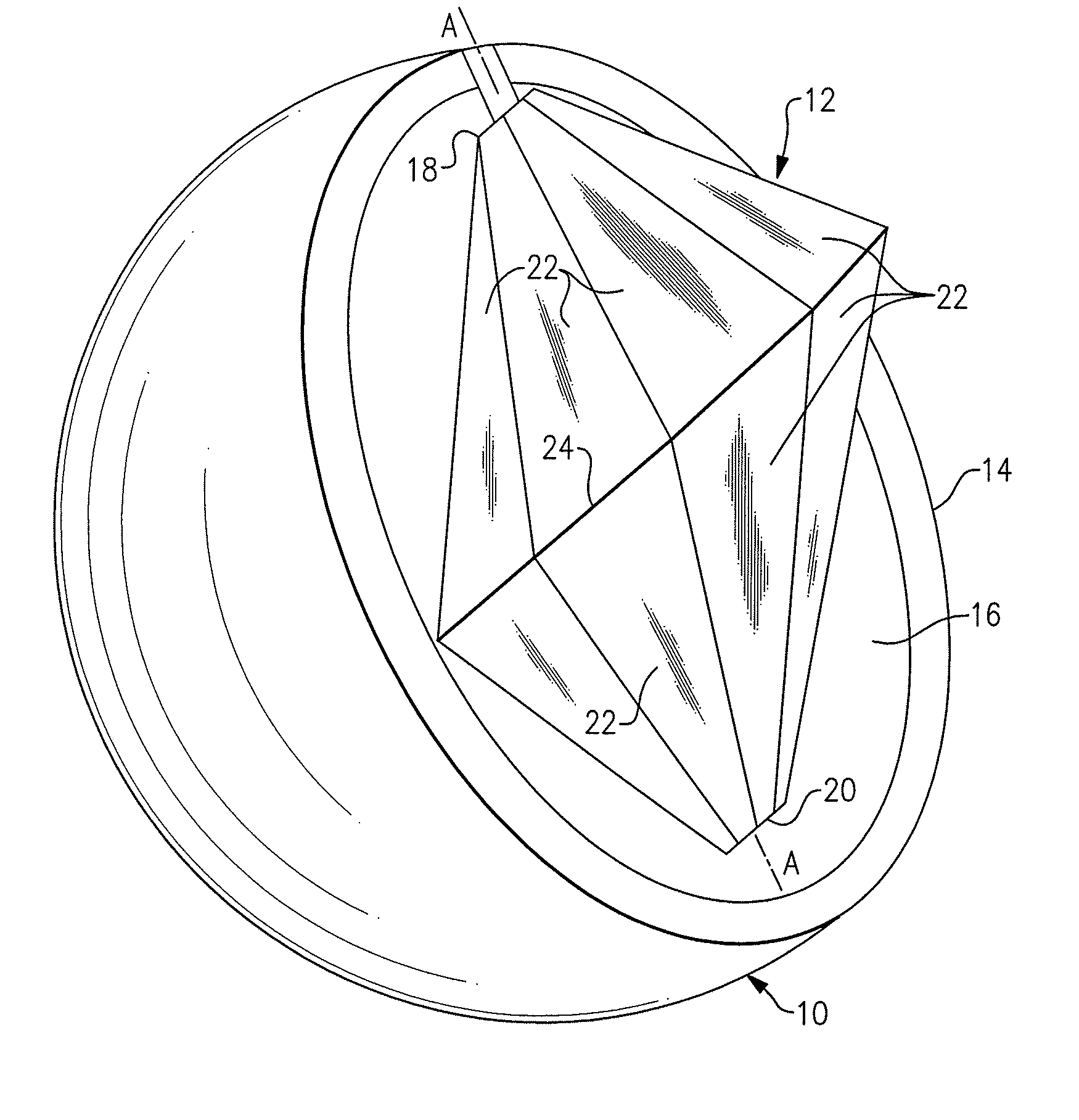
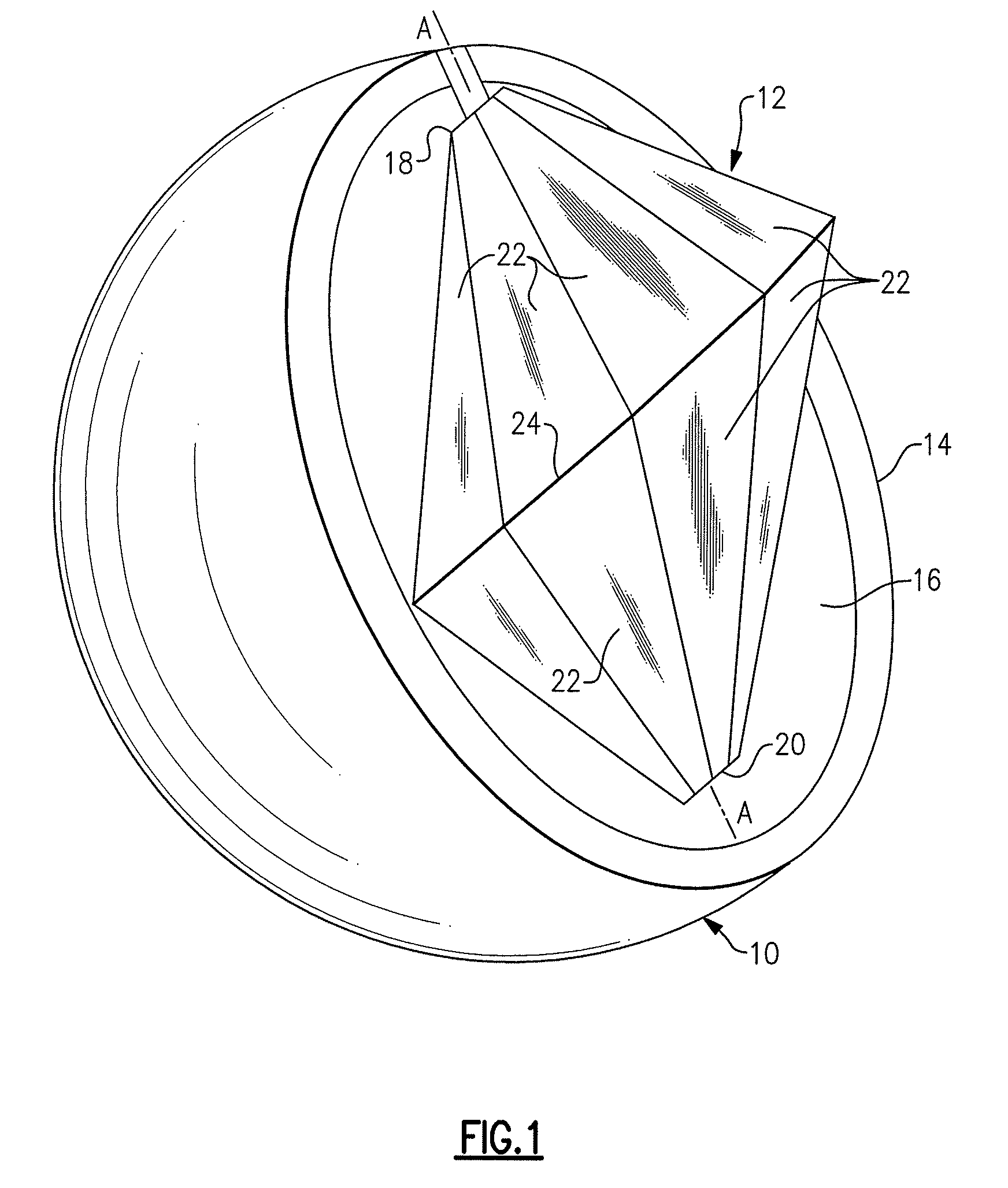
[0007]In FIG. 1 is shown a bowing ball, denoted generally by reference numeral 10, internally incorporating weight block 12, incorporating the present invention. Ball 10 includes spherical outer shell 14 enclosing core 16 which may be of the same or different material as shell 14. Grip holes are drilled in conventional fashion in the outer surface of ball 10 to fit the grip of an individual who will use the ball.

[0008]Weight block 12 is seen to have two ends 18 and 20 with a central axis A-A extending through both ends. In the illustrated embodiment, the outer surface of block 12 is formed of a plurality of adjacent, flat segments 22 which taper outwardly from both of ends 18 and 20 to meet at an intermediate plane defined by peripheral boundary 24. As is particularly evident in FIG. 2, the flat plane surrounded by boundary 24 is skewed or angled with respect to axis A-A. That is, rather than lying in a plane normal to the axis, the plane surrounded by boundary 24 is arranged at an ...


PUM


Abstract

A bowling ball having an asymmetrical weight block with respect to its central axis. The weight block has a pair of ends through which the central axis of the block extends, and a medial portion which is offset or skewed with respect to the weight block axis. The block has an outer surface which has a maximum cross section in at least one plane intersected by the central axis intermediate of the two ends. The plane is intersected by the central axis and is enclosed by a boundary defining the largest transverse cross section of the block not normal to the central axis. The medial plane is disposed at an angle of between about 22.5° and 90° with respect to the central axis of the block.

Description

BACKGROUND OF THE INVENTION[0001]The present invention relates to bowling balls, and more particularly to bowling balls incorporating an internal weight block of novel configuration for effecting ball performance in a positive manner.[0002]Weight blocks of various sizes and shapes have been incorporated in bowling balls in order to alter the performance of the ball as it travels down the alley and impacts the pins. Such blocks are disclosed, for example, in U.S. Pat. No. 5,238,245 and its Reissue (Re. 35,448), of the present applicant, as well as U.S. Pat. Nos. 5,037,096, 5,389,042, and 6,027,412 all of Pine et al. The weight blocks may be of essentially symmetrical form and incorporated in the ball with the geometric center of the ball and the weight block coincident, or with the weight block and / or its position within the ball symmetrical.SUMMARY OF THE INVENTION[0003]The weight block of the present invention is asymmetrical with respect to a central axis. That is, the weight bloc...

Claims


Application Information

Patent Timeline
Patent Type & Authority Patents(United States)
IPC IPC(8): A63B37/06
CPCA63B37/0001A63B37/10
Inventor SPOSATO, RICHARD
Owner LANE NO 1
Learn More