Display having self-orienting mounting area

a display and mounting area technology, applied in the direction of machine supports, mechanical actuation of burglar alarms, instruments, etc., can solve the problem of creating quite a disorderly appearance, and achieve the effect of facilitating viewing and handling of display items

Inactive Publication Date: 2010-06-22
INVUE SECURITY PROD INC
View PDF10 Cites 46 Cited by
  • Summary
  • Abstract
  • Description
  • Claims
  • Application Information

AI Technical Summary

Problems solved by technology

This often becomes a problem when a potential customer picks up an item of merchandise such as a cell phone or camera in order to look it over and see how it feels, and then places the item generally in the display area from which it was obtained but in a haphazard manner.
Especially because multiple items of such merchandise are displayed near one another, when they are all replaced haphazardly, it creates quite a disorderly appearance.

Method used


Image

  • Display having self-orienting mounting area
  • Display having self-orienting mounting area
  • Display having self-orienting mounting area

Examples


Embodiment Construction

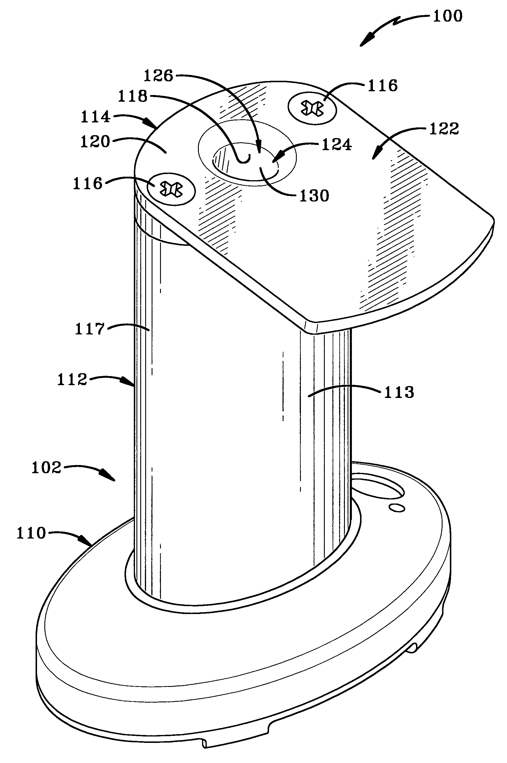
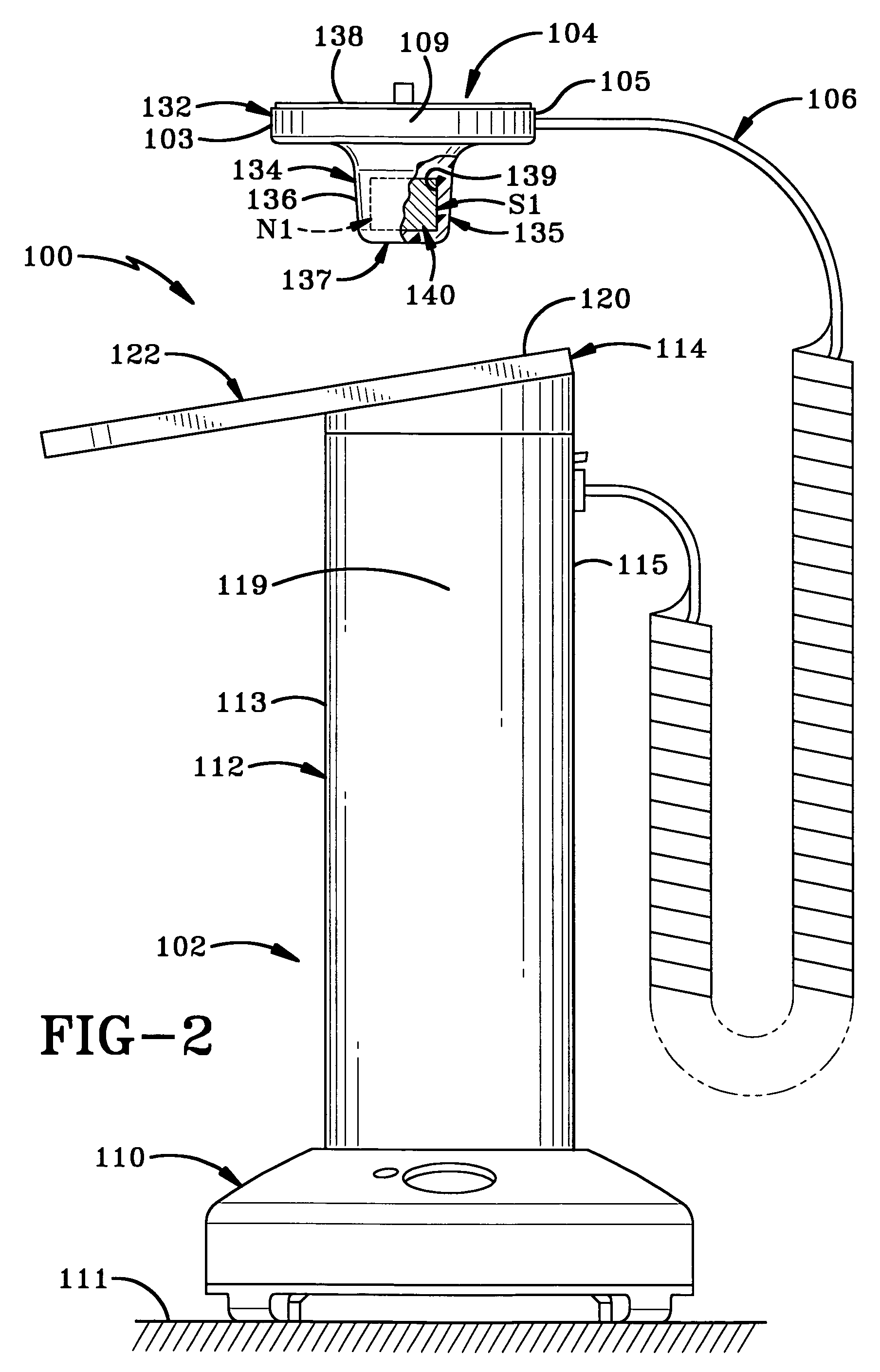
[0023]A first embodiment of the display assembly or display stand of the present invention is indicated generally at 100 in FIGS. 1-2; and a second embodiment is indicated generally at 200 in FIGS. 9-11. Referring to FIGS. 1-2, stand 100 includes a base 102, a mounting member 104 which is removably mountable on base 102 and a tether 106 which is connected to and extends between base 102 and mounting member 104. Mounting member 104 has a front 103, an opposed rear 105 and first and second sides 107 and 109, which are noted herein primarily as points of reference to clarify the movement of mounting member 104 as later detailed. Mounting member 104 is configured for mounting thereon an item of merchandise or display item such as cell phone 108 (FIG. 3) in order to allow the item of merchandise to be moved away from base 102 in order to view and handle said item. Base 102 includes a foundation 110 which is seated on a support surface 111, an upwardly projecting column 112 which extends ...


PUM


Abstract

A display assembly for automatically orienting a display item includes a base and a mounting member for mounting thereon the display item. The mounting member is removably mounted on the base to allow handling of the display item when removed and when mounted automatically moves from an unaligned orientation to an aligned display orientation. One alignment mechanism is magnetically operable and preferably includes first and second magnets respectively mounted on the base and mounting member wherein north and south poles of the first magnet align respectively with south and north poles of the second magnet to align the mounting member in the display orientation. Another alignment mechanism includes at least one camming surface for facilitating alignment of the mounting member and preferably camming surfaces respectively on the base and the mounting member which engage one another to facilitate to alignment.

Description

CROSS REFERENCE TO RELATED APPLICATIONS[0001]This application claims priority from U.S. Provisional Application Ser. No. 60 / 754,138 filed Dec. 27, 2005; the disclosure of which is incorporated herein by reference.BACKGROUND OF THE INVENTION[0002]1. Technical Field[0003]The invention relates generally to display stands for merchandise. More particularly, the invention relates to a display stand which allows the handling of an item of merchandise. Specifically, the invention relates to such a display stand which orients the item of merchandise to a desired display orientation after the handling thereof.[0004]2. Background Information[0005]Amongst the great variety of display structures used to display items of merchandise are those which allow a potential customer to handle and view the item of merchandise in order to determine if it has characteristics desirable to the potential customer. This is commonly the case for displaying various types of electronic articles such as cell phone...

Claims


Application Information

Patent Timeline
Patent Type & Authority Patents(United States)
IPC IPC(8): F16M11/02
CPCA47F7/024F16M11/041F16M11/22F16M11/12F16M11/08
Inventor MARSILIO, RONALD M.BELDEN, JR., DENNIS D.
Owner INVUE SECURITY PROD INC
Why Eureka
Try Eureka