Axial fan motor
a technology of axial fan and motor, which is applied in the direction of dynamo-electric machines, structural associations, supports/encloses/casings, etc., can solve the problems of increasing the noise of electromagnetic exciting force, the inability to recycle resources, and the inability to rotate the vanes in the axial fan. , to achieve the effect of reducing structural noise and reducing nois
- Summary
- Abstract
- Description
- Claims
- Application Information
AI Technical Summary
Benefits of technology
Problems solved by technology
Method used
Image
Examples
first preferred embodiment
[0063]First, a first preferred embodiment of the present invention is described with reference to FIGS. 1 to 9. In addition, the same reference numerals in the respective figures denote the same parts.
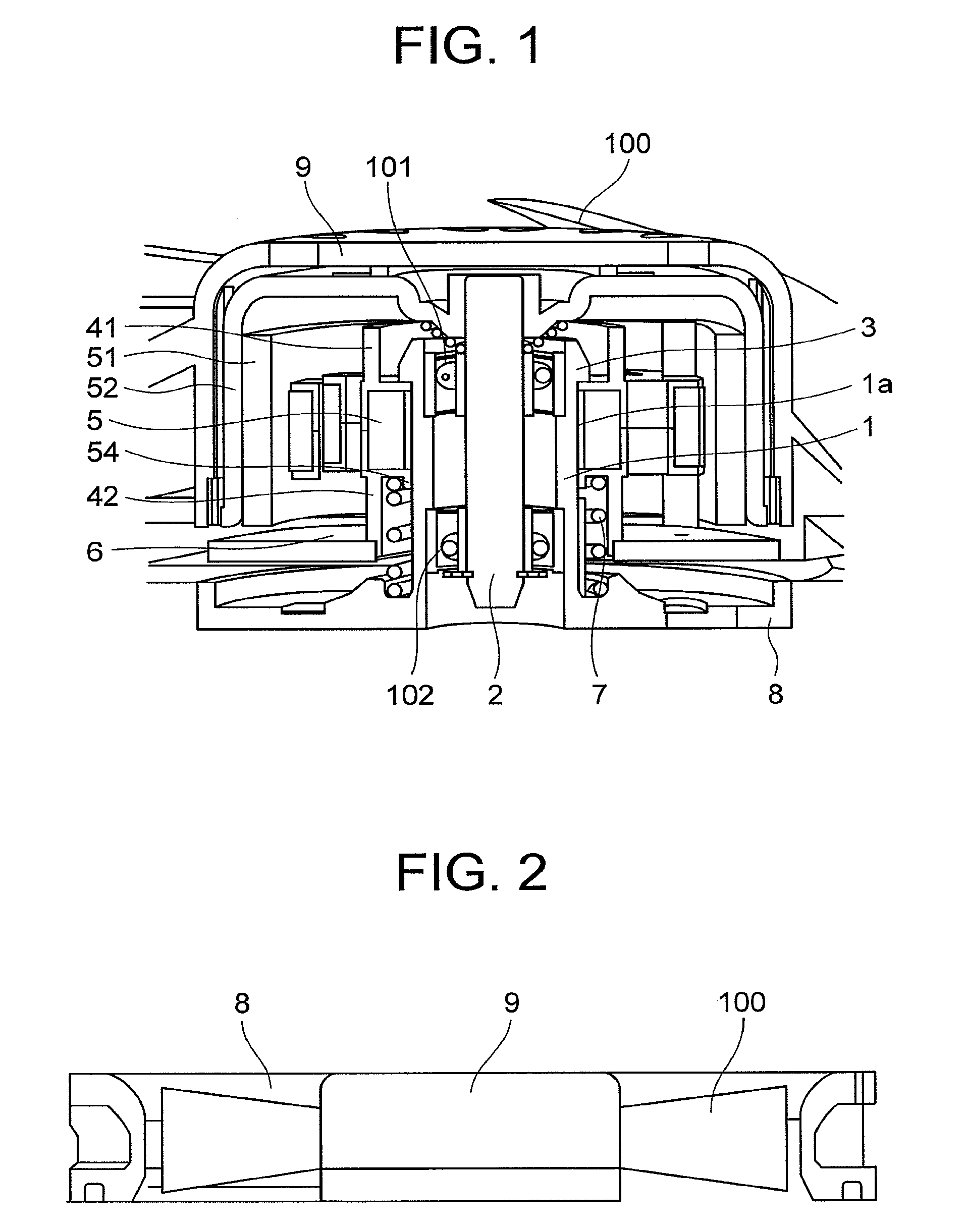
[0064]FIG. 1 is a cross sectional view showing an axial fan motor according to a first preferred embodiment of the present invention.
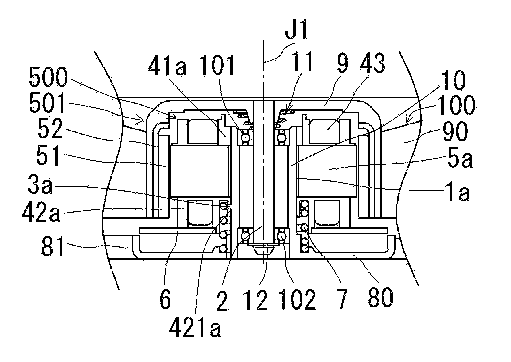
[0065]FIG. 2 is a view showing an entire construction of the axial fan motor according to the first preferred embodiment of the present invention. In FIGS. 1 and 2, the reference numeral 1 denotes a sleeve through which a rotating shaft 2 of the axial fan motor extends. The reference numeral 3 denotes stoppers mounted to a tip end of the sleeve 1. The shaft 2 and the sleeve 1 are mounted with bearings 101, 102 therebetween. The reference numeral 41 denotes an upper insulator and 42 a lower insulator. The reference numeral 5 denotes a stator core and a fan to which a rotor including a magnet 51 and a rotor case 52 is provided, the fan being mounted to an o...
second preferred embodiment
[0078]Next, a second preferred embodiment of the present invention will be described with reference to FIGS. 10 to 13. In addition, the same reference numerals in the respective drawings denote the same parts.
[0079]FIG. 10 is a perspective view of a venturi. As shown in FIG. 10, an upper end of a sleeve 1 mounted to a central portion of the venturi 8 is circular-shaped and downwardly concave-shaped and is provided on a portion of a circumference thereof with a positioning notch 111. An upper insulator described below is fitted into the circular-shaped recess.
[0080]FIG. 11 is a perspective view of the upper insulator 41. The upper insulator 41 is provided with a bearing support 413. A bearing is fitted inside the bearing support 413.
[0081]FIG. 12 is a perspective view of the upper insulator 41 as viewed from below. As shown in FIG. 12, a positioning projection 414 is mounted to an underside of the upper insulator 41 to be fitted into the notch 111 on the upper portion of the sleeve s...
third preferred embodiment
[0087]Subsequently, a third preferred embodiment of the present invention will be described with reference to FIG. 14 to 18. In addition, the same reference numerals in the respective drawings denote the same parts.
[0088]FIG. 14 is a perspective view of a venturi. As shown in FIG. 14, an upper end of a sleeve 1 mounted to a central portion of the venturi 8 is circular-shaped and downwardly concave-shaped to include large and small semi-circular notches in eight locations on a circumference thereof. The notches will be described with reference to an enlarged perspective view of FIG. 15, which shows the vicinity of the sleeve 1. As shown in FIG. 15, two kinds of semi-circular notches are shown; passage notches 112 and positioning notches 113 are provided, and the positioning notches 113 have a smaller radius than the radius of the passage notches 112. Two of these notches define a set and are arranged very close to each other, four sets in total being arranged across from each other, ...
PUM
 Abstract
Description
Claims
Application Information
 - R&D
- Intellectual Property
- Life Sciences
- Materials
- Tech Scout
- Unparalleled Data Quality
- Higher Quality Content
- 60% Fewer Hallucinations
Browse by: Latest US Patents, China's latest patents, Technical Efficacy Thesaurus, Application Domain, Technology Topic, Popular Technical Reports.
© 2025 PatSnap. All rights reserved.Legal|Privacy policy|Modern Slavery Act Transparency Statement|Sitemap|About US| Contact US: help@patsnap.com


