Superconducting homopolar inductor alternator for power applications

a superconducting, homopolar inductor technology, applied in the direction of machines/engines, efficient propulsion technologies, mechanical equipment, etc., can solve the problems of limiting the application of the same, reducing the performance of the superconductor, and reducing the efficiency of the superconductor

Inactive Publication Date: 2010-06-08
GENERAL ELECTRIC CO
View PDF12 Cites 6 Cited by
  • Summary
  • Abstract
  • Description
  • Claims
  • Application Information

AI Technical Summary

Problems solved by technology

Accordingly, designing, fabricating and operating such a rotor may be difficult.
Specifically, because the coils are coupled to the rotor, the coils may be subjected to centrifugal forces that may cause strains and degrade the performance of the superconductor.
Further, the performance of these machines limits the application of the same.

Method used


Image

  • Superconducting homopolar inductor alternator for power applications
  • Superconducting homopolar inductor alternator for power applications
  • Superconducting homopolar inductor alternator for power applications

Examples


Embodiment Construction

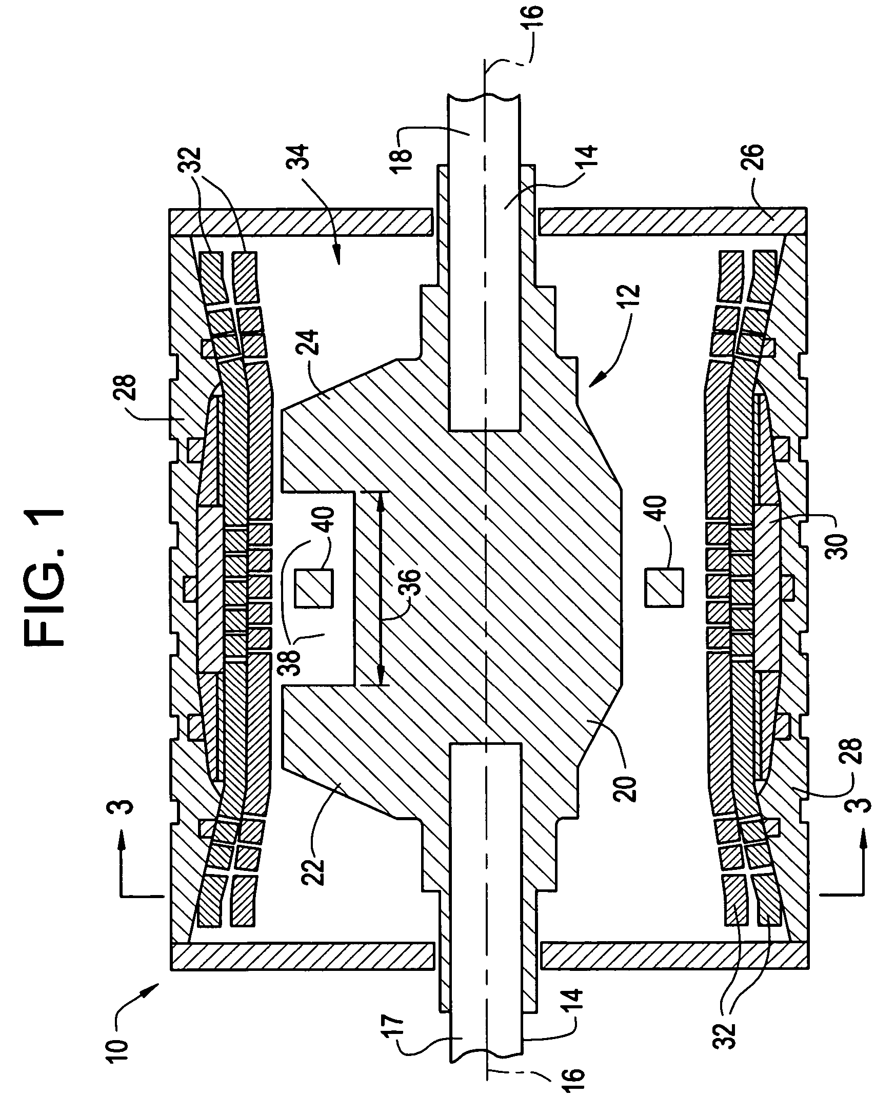
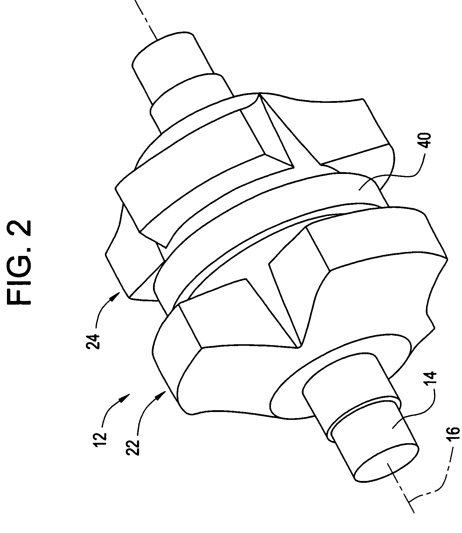
[0016]FIG. 1 is a side partial cross-sectional view of an exemplary embodiment of a homopolar electrical machine 10 that includes a rotor 12 with a shaft 14 having a longitudinal axis 16. Rotor 12 is rotatable about axis 16. In the exemplary embodiment, shaft 14 is segmented such that a first shaft stub 17 and a second shaft stub 18 form shaft 14. Rotor 12 also includes a pole piece assembly 20 that includes a plurality of first pole pieces 22 that are separated axially on pole piece assembly 20 from a plurality of second pole pieces 24. In an alternative embodiment, rotor 12 is formed as a single monolithic structure that includes first pole pieces 22 and second pole pieces 24, axially separated and coupled to shaft 14. In another alternative embodiment, pole piece assembly 20, first pole pieces 22 and / or second pole pieces 24 are integrally formed with shaft 14 to define a monolithic rotor. In the exemplary embodiment, only one pole piece assembly 20 is illustrated. It should be u...


PUM


Abstract

A portable power system has a turbine engine generating mechanical energy. A homopolar electrical machine receives this energy. The homopolar electrical machine has a single stationary superconducting field coil configured to create a magnetic field. A homopolar rotor is configured to rotate within the magnetic field such that a rotating magnetic field is created in a stationary winding by interaction of the rotating permeance wave produced by the homopolar rotor and the magnetic field produced by the single stationary field coil. The homopolar electrical machine is configured as a generator and produces electrical power for the portable power system.

Description

BACKGROUND OF THE INVENTION[0001]The disclosed systems generally relate to the application of electrical motors / generators and more particularly to homopolar machines including superconducting windings.[0002]Historically, most superconducting electric machines have included a superconducting field coil installed on the rotor. The superconducting coil is maintained at a temperature approaching zero Kelvin using a continuous supply of cryogenic fluid such as, but not limited to, helium (He). If a high temperature superconductor (HTS) is used in fabricating the field coil, a cryogenic fluid such as nitrogen (N2) may be used to achieve superconducting temperatures. The cryogenic fluid is typically supplied to the superconducting field coil from a stationary cryocooler through a transfer coupling that is coupled to one end of the rotor. The transfer coupling channels the cryogenic fluid from a stationary portion to a rotating portion on the rotor. The cryogenic fluid is then routed throu...

Claims


Application Information

Patent Timeline
Patent Type & Authority Patents(United States)
IPC IPC(8): H02K55/06
CPCF01D15/10H02K55/06H02K7/1823H02K7/183H02K7/1838Y02E40/627Y02T50/671F05D2220/50Y02E40/60Y02T50/60
Inventor SIVASUBRAMANIAM, KIRUBAHARANLASKARIS, EVANGELOS TRIFONBRAY, JAMES WILLIAMFOGARTY, JAMES MICHAEL
Owner GENERAL ELECTRIC CO
Why Eureka
Try Eureka