
Electric pencil sharpener

a technology of electric pencils and sharpeners, which is applied in the direction of sharpeners, printing, manufacturing tools, etc., can solve the problems of high manufacturing cost and inconvenient operation of such electric pencil sharpeners by peopl

Inactive Publication Date: 2010-06-01
WAN CHUNG PAK
View PDF3 Cites 4 Cited by
  • Summary
  • Abstract
  • Description
  • Claims
  • Application Information

AI Technical Summary

Benefits of technology

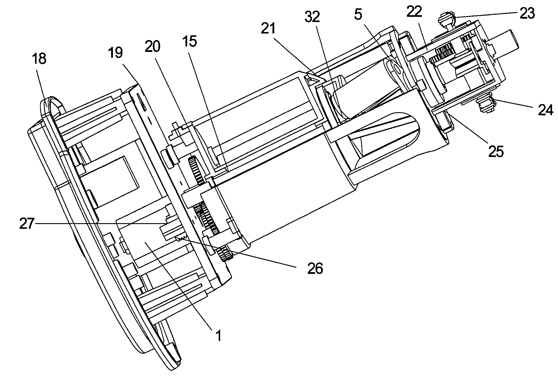
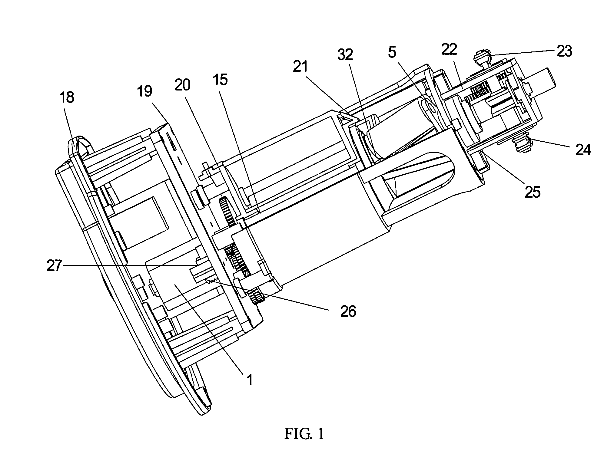
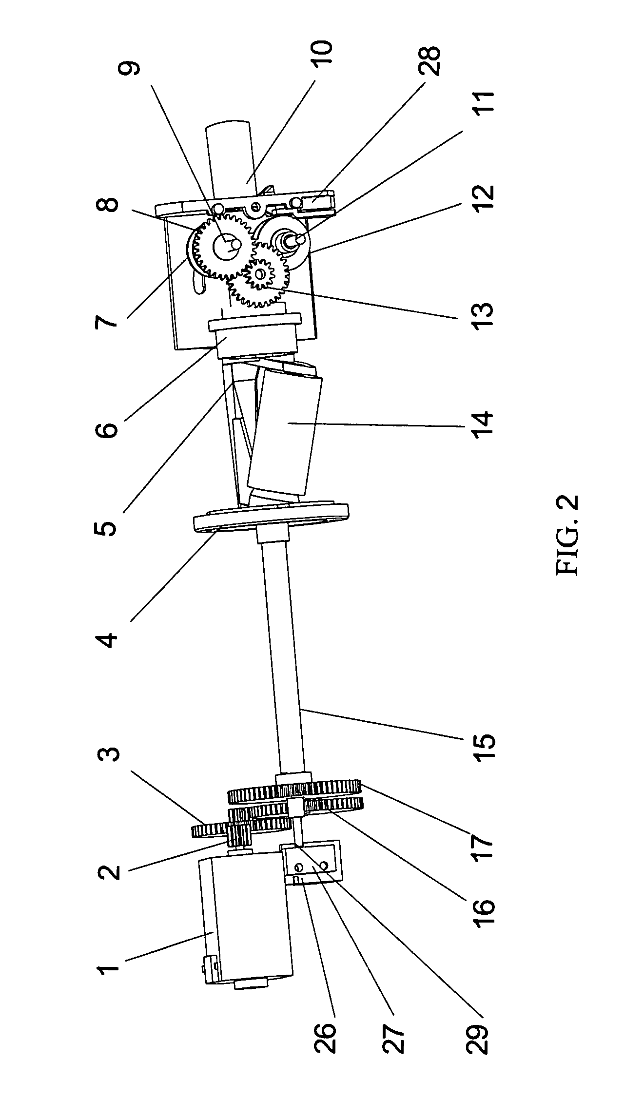
[0008]In one aspect of the present invention, an improved electric pencil sharpener is provided includes a motor, a transmission subassembly driven by the motor, a cutter subassembly driven by the transmission subassembly, a feeding subassembly driven by the cutter subassembly and at least one resilient adjusting means. The feeding subassembly includes a pair of feeding rollers movablely supported on two brackets arranged in parallel position, defining a feeding space therebetween. The at least one resilient means connects the two feeding rollers and is capable of automatically adjusting the interval between the two feeding rollers so as to conveniently sharpen pencils with different diameter.
[0011]In further aspect of the present invention, an improved electric pencil sharpener is disclosed combining a motor, a transmission subassembly driven by the motor, a cutter subassembly driven by the transmission subassembly, a feeding subassembly driven by the cutter subassembly, at least one resilient adjusting means and an electric controlling system. The electric controlling system includes a startup switch, triggering means and reverse switch under control of the triggering means for driving the motor to rotate in a reverse direction, so that render the electric pencil sharpener capable of self-feeding while sharpening the pencil and self-retreating after the pencil is processed.

Problems solved by technology

However, the adjusting assembly in the conventional electric pencil sharpener is so sophisticated, that results in high manufacturing cost.
Moreover, the interval adjustment between the two feeding rollers is under manual operation, which is inconvenient for people to operate such electric pencil sharpener.

Method used


Image

  • Electric pencil sharpener
  • Electric pencil sharpener
  • Electric pencil sharpener

Examples


Embodiment Construction

” one will understand how the features of the system and methods provide several advantages over traditional electric pencil sharpeners.

[0008]In one aspect of the present invention, an improved electric pencil sharpener is provided includes a motor, a transmission subassembly driven by the motor, a cutter subassembly driven by the transmission subassembly, a feeding subassembly driven by the cutter subassembly and at least one resilient adjusting means. The feeding subassembly includes a pair of feeding rollers movablely supported on two brackets arranged in parallel position, defining a feeding space therebetween. The at least one resilient means connects the two feeding rollers and is capable of automatically adjusting the interval between the two feeding rollers so as to conveniently sharpen pencils with different diameter.

[0009]In another aspect of the present invention, an improved electric pencil sharpener is disclosed engaging one resilient adjusting means, connecting the two...


PUM


Abstract

An electric pencil sharpener includes a motor, a transmission subassembly and a cutter subassembly driven by the motor, a feeding subassembly and at least one resilient adjusting means. The feeding subassembly includes a feeding gear set coupled to the transmission subassembly and two feeding rollers adapted to sandwich a pencil to be sharpened, at least one feeding roller is driven by the feeding gear set. The pair of brackets is arranged in parallel, respectively defining slide ways to movablely support the feeding rollers. A feeding space is defined between the two brackets. The at least one resilient adjusting means connects the two feeding rollers outside or inside the feeding space, adapted for keeping the feeding rollers nipping the pencil and engendering a pencil feeding friction.

Description

BACKGROUND OF THE INVENTION[0001]1. Field of the Invention[0002]The present invention generally relates to an office product, electric pencil sharpener, more particularly the present invention relates to an improved electric pencil sharpener provided with a feeding subassembly with a pair of feeding rollers, which space between the two feeding rollers is automatically adjustable. A further novel element of the invention is the provision for an electric pencil sharpener capable of automatic sharpening and feeding different pencils with different sizes.[0003]2. Background of the Invention[0004]Pencil sharpener is a necessary tool in the modern office. Electric pencil sharpeners are in widespread use largely due to their modest price and outstanding reliability. A typical electric pencil sharpeners comprises an electric motor, a gear train, a cutter assembly, and a receptacle receiving a pencil or a pencil alignment subassembly, and a switch for activating the motor, e.g. upon insertio...

Claims


Application Information

Patent Timeline
Patent Type & Authority Patents(United States)
IPC IPC(8): B43L23/00
CPCB43L23/002B43L23/02B43L23/008
Inventor HU, JINGYI
Owner WAN CHUNG PAK
Learn More