
Slide rail

a technology of slide rail and slide plate, which is applied in the direction of washstands, lighting supports, and accessories of scaffolds, can solve the problems of inconvenient use of conventional slide rails, and achieve the effect of conveniently holding sanitary devices

Inactive Publication Date: 2010-05-25
SHENG TAI BRASSWARE
View PDF19 Cites 35 Cited by
  • Summary
  • Abstract
  • Description
  • Claims
  • Application Information

AI Technical Summary

Benefits of technology

"The present invention provides a slide rail for holding sanitary devices conveniently. The slide rail has a mounting shaft and a sliding mount with a clamp, handle, clamp jaw, holding bracket, and spring. The clamp is mounted around the mounting shaft and has a lock bar and grip. The holding bracket is connected to the clamp to hold a showerhead or soap dish and has a positioning ring. The spring is mounted in the clamp to push the convex surface of the clamp jaw to engage an engaging recess of the lock bar to hold the sliding mount with the mounting shaft. The technical effects of the invention are that it provides a convenient way to hold sanitary devices and ensures easy cleaning and maintenance."

Problems solved by technology

Then, the conventional slide rail is inconvenient in use.

Method used


Image

  • Slide rail
  • Slide rail
  • Slide rail

Examples


Embodiment Construction

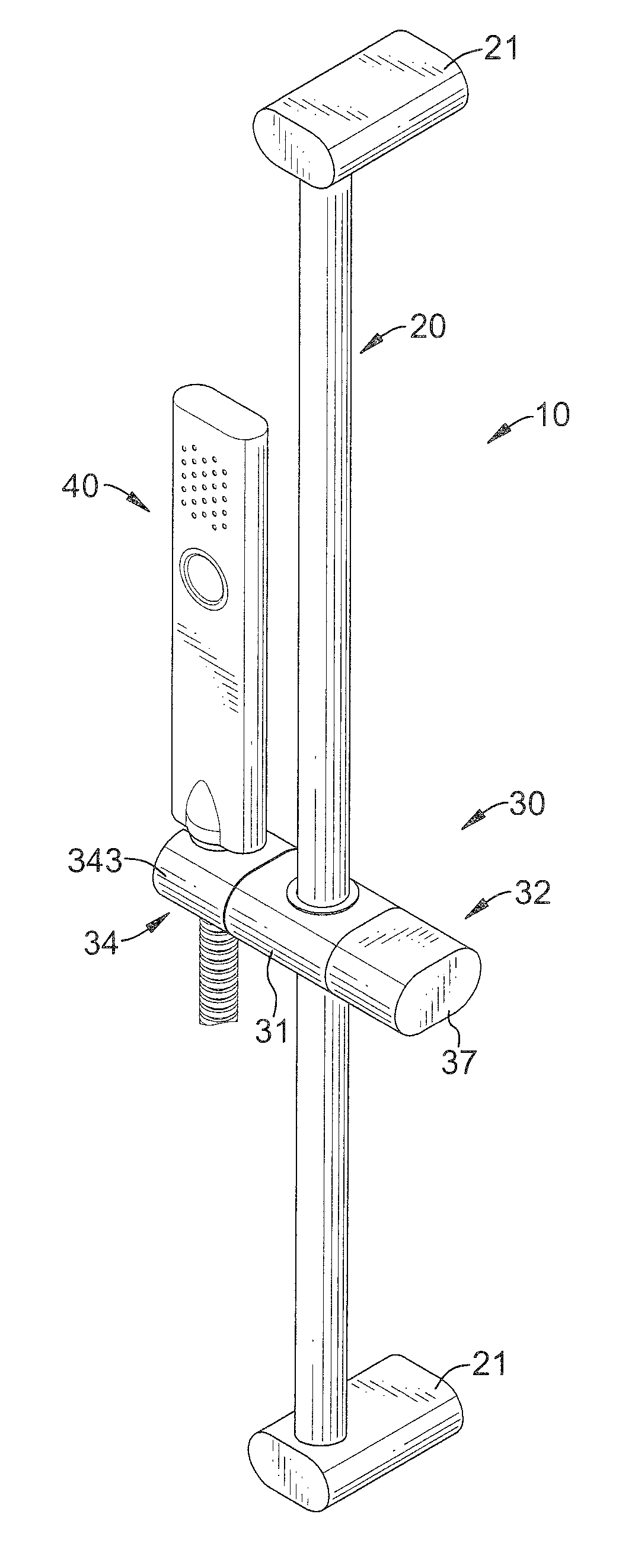
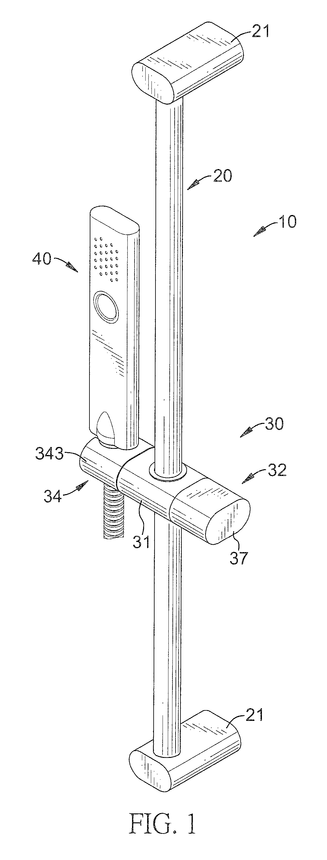
[0023]With reference to FIGS. 1 to 3, a slide rail (10) in accordance with the present invention comprises a mounting shaft (20) and a sliding mount (30).

[0024]The mounting shaft (20) is mounted on a wall and has an external surface, two ends, a diameter and two mounting blocks (21). The mounting blocks (21) are respectively formed on the ends of the mounting shaft (20) and are mounted on a wall.

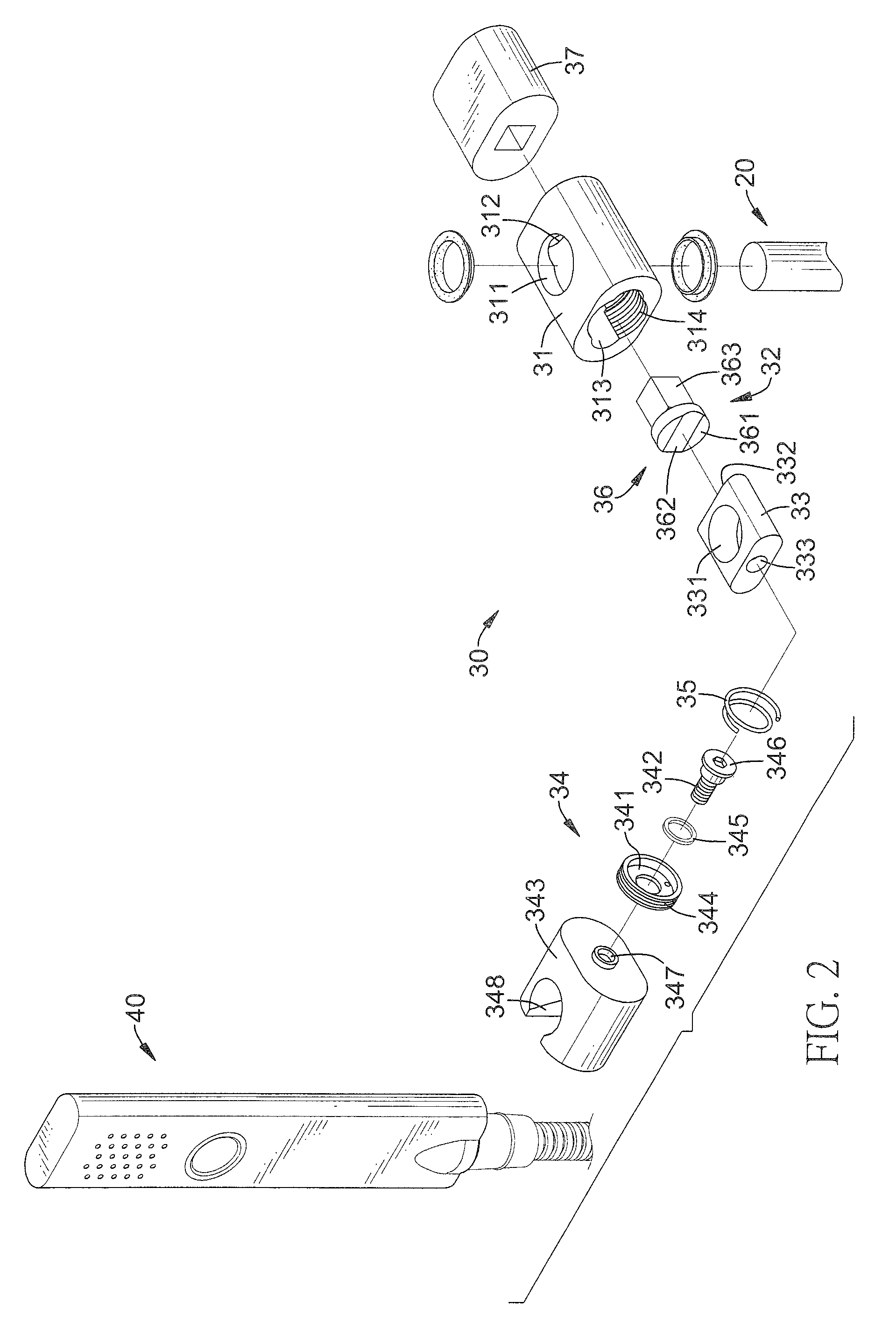
[0025]The sliding mount (30) is movably mounted around the mounting shaft (20) and has a clamp (31), a handle (32), a clamp jaw (33), a holding bracket (34) and a spring (35).

[0026]The clamp (31) may be hollow and elliptical in cross section, is mounted slidably around the mounting shaft (20) and has two mounting surfaces, two ends, an internal surface, two mounting holes (311), two washers, a connecting hole (312), an attaching hole (313) and an inner thread (314). The mounting holes (311) are respectively formed through the mounting surfaces of the clamp (31) aligned with each other and ar...


PUM


Abstract

A slide rail has a mounting shaft and a sliding mount. The sliding mount is movably mounted around the mounting shaft and has a clamp, a handle, a clamp jaw, a holding bracket and a spring. The clamp is mounted around the mounting shaft. The handle is rotatably connected to the clamp and has a lock bar and a grip. The clamp jaw is mounted around and abuts the mounting shaft in the clamp and has a convex surface. The holding bracket is connected to the clamp to hold a showerhead, a soap dish or the like and has a positioning ring. The spring is mounted in the clamp between the clamp jaw and the positioning ring to push the convex surface of the clamp jaw to engage an engaging recess of the lock bar.

Description

BACKGROUND OF THE INVENTION[0001]1. Field of the Invention[0002]The present invention relates to a slide rail, more particular to a slide rail for holding sanitary devices conveniently.[0003]2. Description of Related Art[0004]With reference to FIG. 7, a conventional slide rail (60) is mounted on a wall for holding sanitary devices such as showerhead, soap dish or the like and has a mounting shaft (61) and a sliding mount (62). The mounting shaft (61) is mounted on a wall and has an external surface and a diameter. The sliding mount (62) is movably mounted around the mounting shaft (61) and has a clamp (63), a holding bracket (64), an handle (65) and a pressing rod (66).[0005]The clamp (63) is hollow, is mounted around the mounting shaft (61) and has a center, two ends, a mounting hole (631) and a connecting hole (632). The mounting hole (631) is formed through the center of the clamp (63) and is mounted around the external surface of the mounting shaft (61). The connecting hole (632...

Claims


Application Information

Patent Timeline
Patent Type & Authority Patents(United States)
IPC IPC(8): A47K3/022A47K3/28
CPCE03C1/066E03C1/06
Inventor HUANG, TING-YAO
Owner SHENG TAI BRASSWARE
Learn More