
Apparatus and method for determining the orientation of an object such as vehicle wheel alignment

a technology for determining the orientation of objects and vehicles, applied in the direction of mechanical measuring arrangements, instruments, using mechanical means, etc., can solve the problems of less accurate than desired, subject to placement error and wear, cumbersome direct measurement methods, etc., and achieves rapid and efficient contact, minimal operator labor, and the effect of determining the position of the wheel/tir

Active Publication Date: 2010-05-04
BURKE E PORTER MACHINERY
View PDF60 Cites 14 Cited by
  • Summary
  • Abstract
  • Description
  • Claims
  • Application Information

AI Technical Summary

Benefits of technology

"The present invention provides an apparatus and method for determining the orientation of a wheel assembly on a vehicle by engaging the wheel assembly with a contact assembly and projecting a beam of light with respect to the contact assembly. The light beam is received by a light beam receiving assembly and formed an image of the light beam indicating the orientation of the wheel assembly with respect to a predetermined position. The apparatus and method can be used to accurately align the wheel assembly and adjust the orientation of the tire and wheel assembly."

Problems solved by technology

Direct measurement methods require human operators or mechanisms to place or mount measurement tools in contact with or to the vehicle and are subject to placement error and wear.
While the prior known direct measurement methods were cumbersome, time-consuming, often labor-intensive, and less accurate than desired, the noncontact or indirect methods often required precisely located, relatively complex light and therefore expensive projectors as well as highly sophisticated calculation methods to determine the wheel and tire position.

Method used


Image

  • Apparatus and method for determining the orientation of an object such as vehicle wheel alignment
  • Apparatus and method for determining the orientation of an object such as vehicle wheel alignment
  • Apparatus and method for determining the orientation of an object such as vehicle wheel alignment

Examples


Embodiment Construction

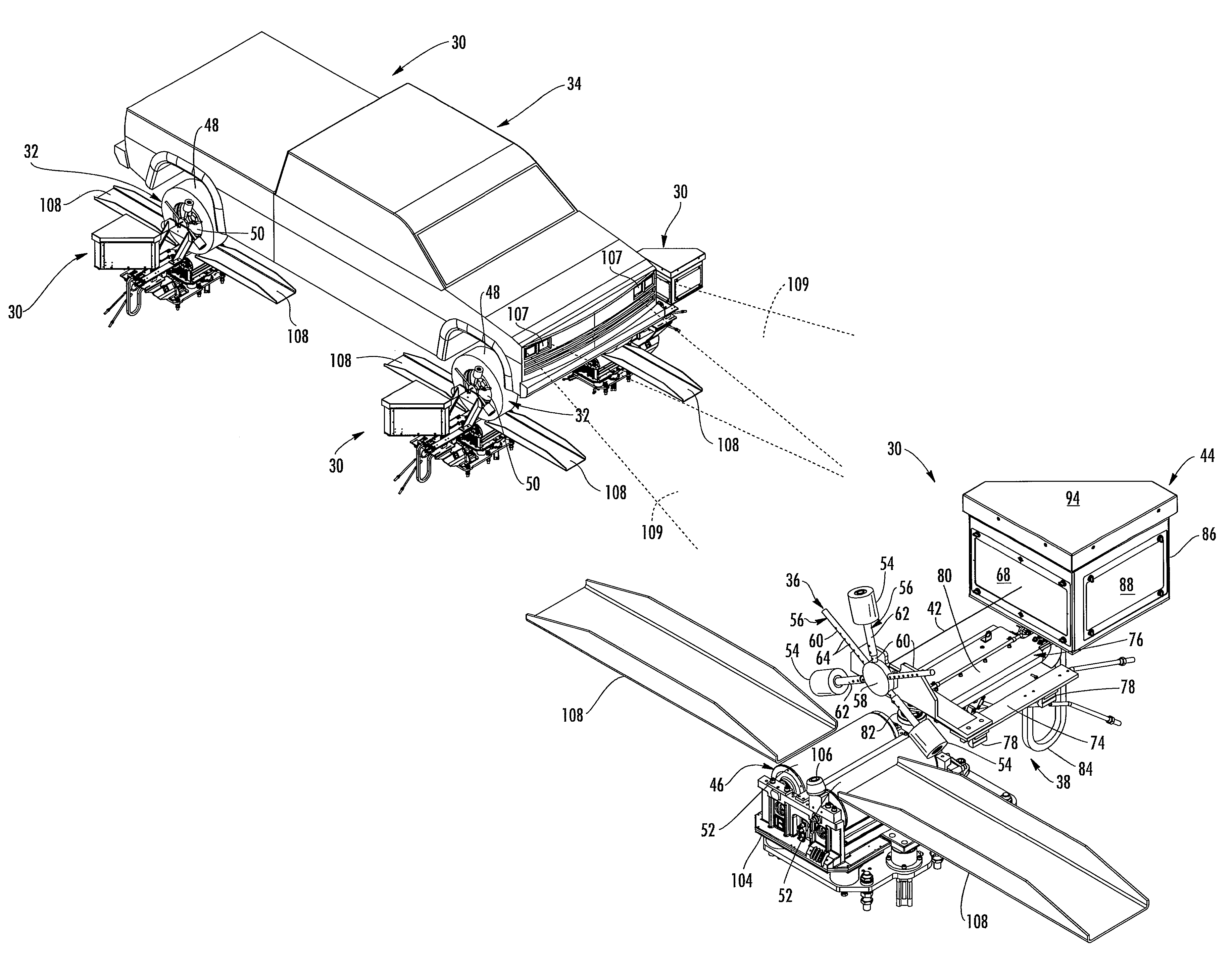
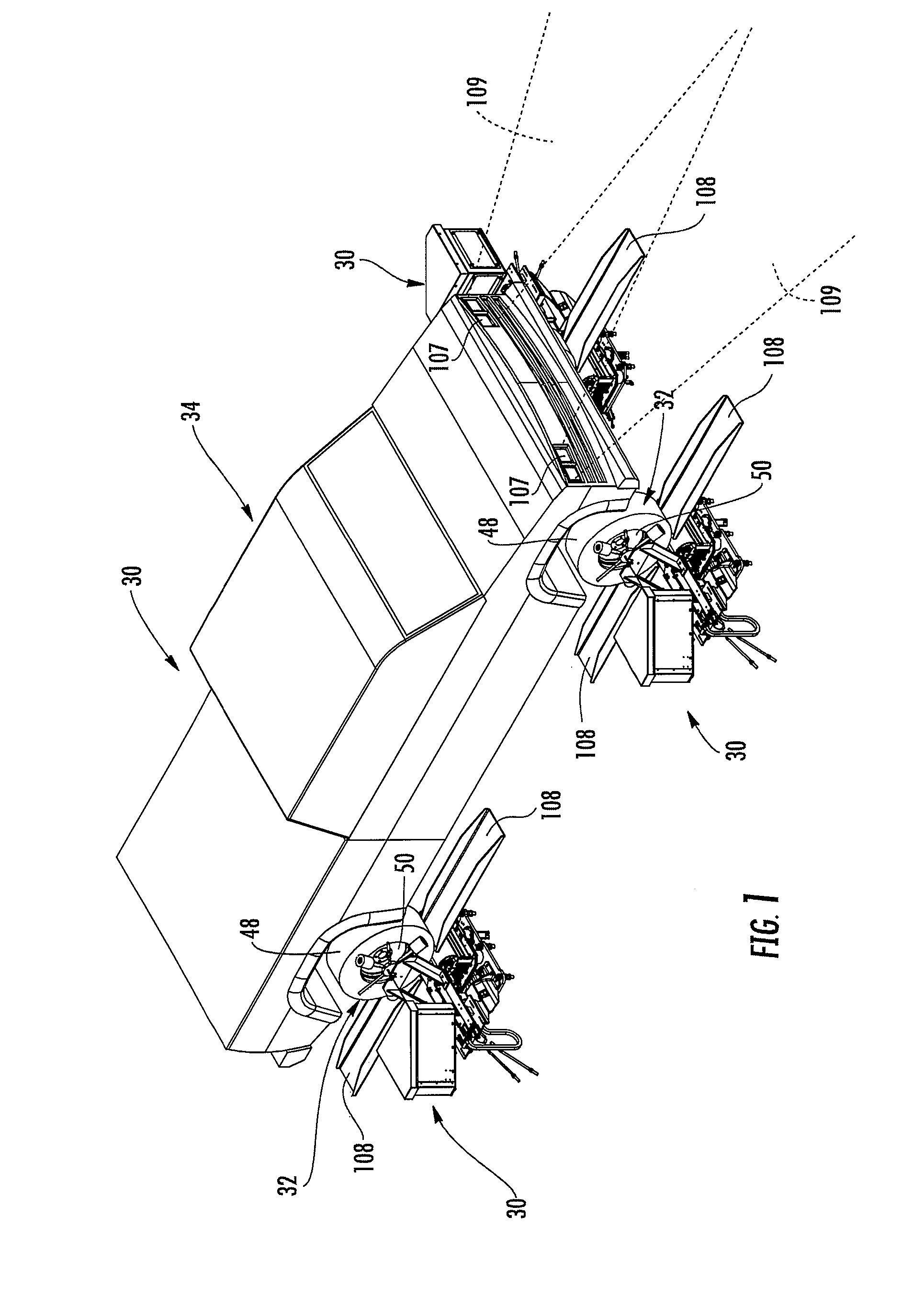
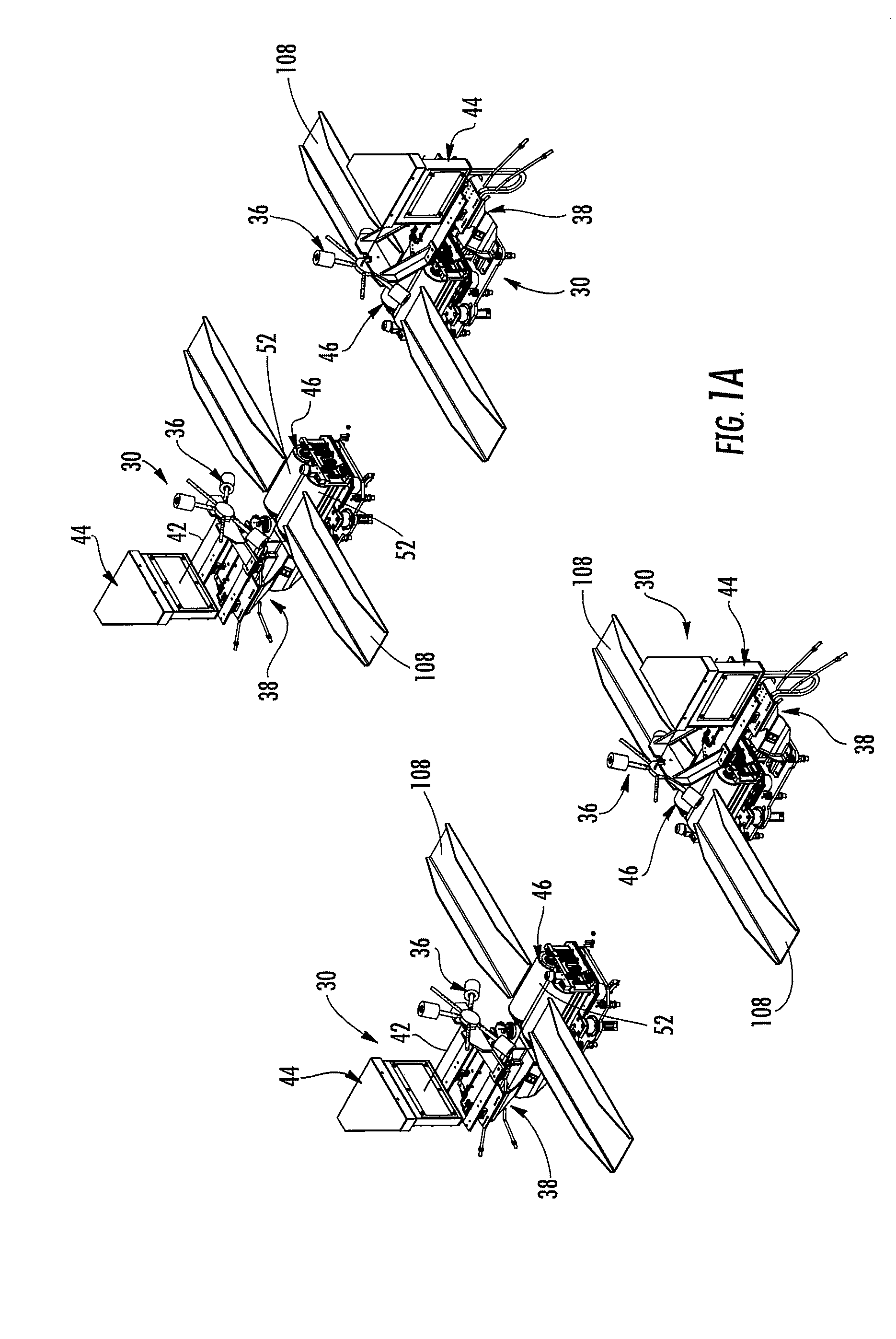
[0043]The present invention will now be described with reference to the accompanying figures, wherein the numbered elements in the following written description correspond to like-numbered elements in the figures. An apparatus for determining the orientation of an object such as a vehicle wheel is shown at 30 in FIGS. 1-3, with a wheel alignment measurement apparatus 30 in operational relation to each of the wheels 32 of vehicle 34. Wheel alignment measurement apparatuses 30 are used to measure the orientation of wheels 32 for adjusting the proper toe and camber of wheels 32 with respect to the vehicle 34 and / or the centerline of the vehicle 34. In the illustrated embodiment, vehicle 34 is a truck, such as a four-wheel drive truck, and apparatuses 30 are used to adjust the toe and / or camber of each of the wheels 32 with respect to the vehicle's centerline.

[0044]As illustrated in FIGS. 4-7, wheel alignment measurement apparatus 30 includes a contact assembly 36 mounted to a positioni...


PUM


Abstract

An apparatus for determining wheel assembly alignment comprises a contact assembly, a light source, and a light beam receiving assembly. The contact assembly engages the wheel assembly to define a plane of orientation of the wheel assembly and the light source projects a beam of light with respect to the contact assembly. The light beam receiving assembly receives the light beam and forms an image of the light beam indicating the orientation of the wheel assembly with respect to a predetermined position. The receiving assembly may include a Fresnel lens for directing the received light beam to a target and a camera device for imaging the light beam on the target, with the camera device adapted to provide toe and camber information of the wheel assembly based on the location at which the light beam impinges upon the target. The contact assembly may be pressed against the wheel assembly without being secured thereto.

Description

CROSS REFERENCE TO RELATED APPLICATION[0001]The present application claims priority of U.S. provisional application, Ser. No. 60 / 816,735 filed Jun. 27, 2006, by Lehman et al. for APPARATUS AND METHOD FOR DETERMINING THE ORIENTATION OF AN OBJECT SUCH AS VEHICLE WHEEL ALIGNMENT, which is hereby incorporated herein by reference in its entirety.FIELD OF THE INVENTION[0002]This invention relates to measurement systems for determining the orientation of a three-dimensional object with respect to a reference system, and more particularly, to a measurement system especially adapted for use with vehicle wheels using a light beam directed from a contact assembly that engages the object or vehicle wheel to define a plane of orientation for the object or wheel to a target with a lens thereby indicating the location of the light beam on the target and, thus, the orientation of the object or wheel with respect to a predetermined position such as the vehicle centerline.BACKGROUND OF THE INVENTION[...

Claims


Application Information

Patent Timeline
Patent Type & Authority Patents(United States)
IPC IPC(8): G01B11/26
CPCG01B11/2755G01C1/04G01B2210/283G01B2210/14G01B11/26G01B13/18G01B21/22G01M17/00
Inventor HOENKE, MARK S.HULBERT, JACK A.LEHMAN, JAMES R.MENKVELD, TODD K.MOMBER, GREGORY J.SMITH, THOMAS D.
Owner BURKE E PORTER MACHINERY
Learn More