
Device and method for treatment of heart valve regurgitation

a technology for heart valves and valves, applied in the field of devices and methods for treating heart valve regurgitation, can solve the problems of increasing affecting the normal operation of the mitral valve, so as to reduce the pathologies of mitral valve regurgitation, reduce the risk of serious complications such as infection or rejection, and reduce the risk of regurgitation. the effect of blood regurgitation

Active Publication Date: 2010-04-27
EDWARDS LIFESCIENCES AG
View PDF70 Cites 258 Cited by
  • Summary
  • Abstract
  • Description
  • Claims
  • Application Information

AI Technical Summary

Benefits of technology

The present invention provides an improved method and device for treating mitral valve regurgitation. The prosthesis device can be delivered and deployed percutaneously within a patient and can dynamically fill gaps between mitral valve leaflets. It can reduce most pathologies of mitral valve regurgitation and can be implanted within a heart to at least partially block gaps that may be present between the two mitral valve leaflets. The device can be used in a method that involves loading a prosthesis within a delivery catheter, advancing the catheter to a chamber of a heart, deploying the coaptation portion within a valve, and supporting it within a commisure of the valve. The device can also include an anchoring member that can be expanded within the valve to position the support member at least partially within the valve. Overall, the invention provides a minimally invasive treatment for mitral valve regurgitation.

Problems solved by technology

Normal operation of the mitral valve can be impaired when the valve leaflets fail to coapt or fully close, allowing regurgitated blood to flow back into the left atrium.
In another example, a mitral valve defect may cause prolapse or a mismatch of the leaflets, allowing blood flow to regurgitate back into the left atrium.
While this treatment procedure has been improved with time, significant limitations still exist.
For example, the removal and replacement of a mitral valve is highly invasive and therefore greatly increases the risk of serious complications such as infection or rejection.
While these techniques require less remodeling than valve replacement, a substantial amount of remodeling is still required.
Further, it can be difficult to evaluate the efficacy of the surgical procedure before the conclusion of the surgery.

Method used


Image

  • Device and method for treatment of heart valve regurgitation
  • Device and method for treatment of heart valve regurgitation
  • Device and method for treatment of heart valve regurgitation

Examples


Embodiment Construction

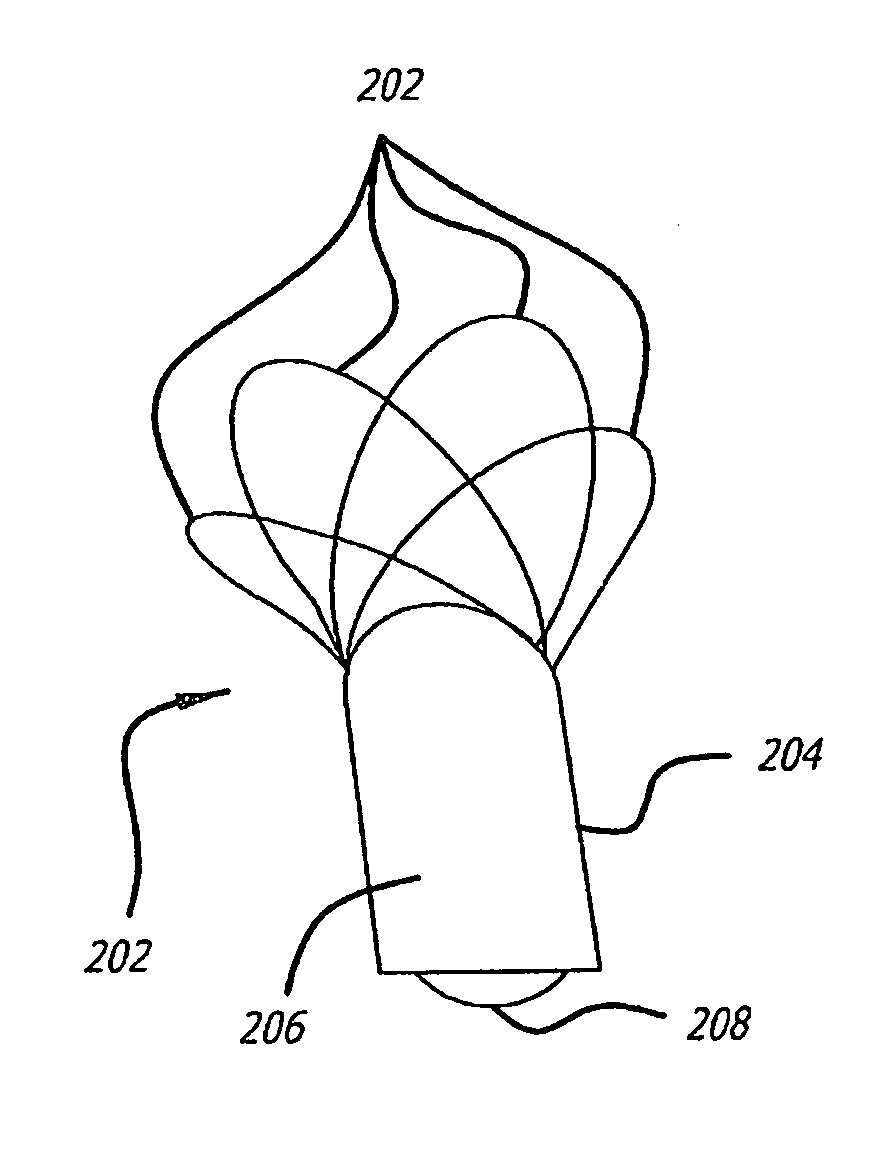
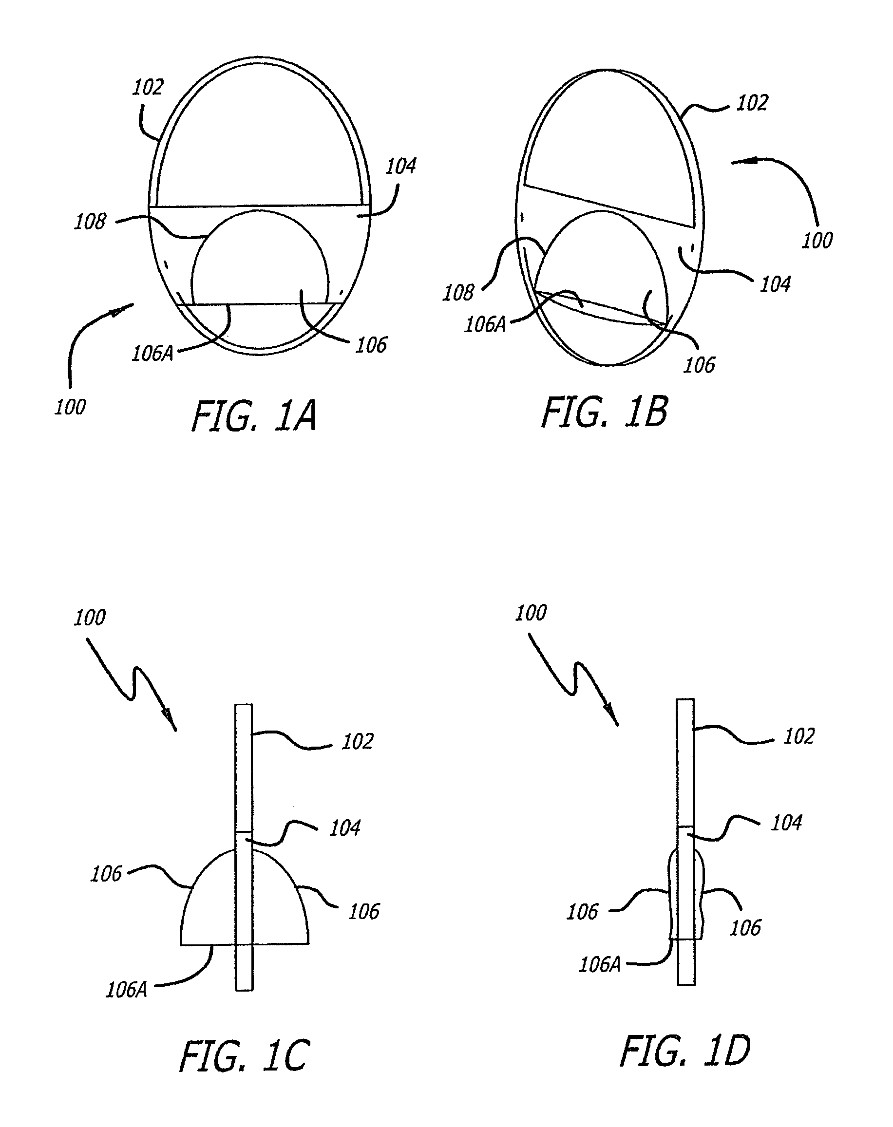
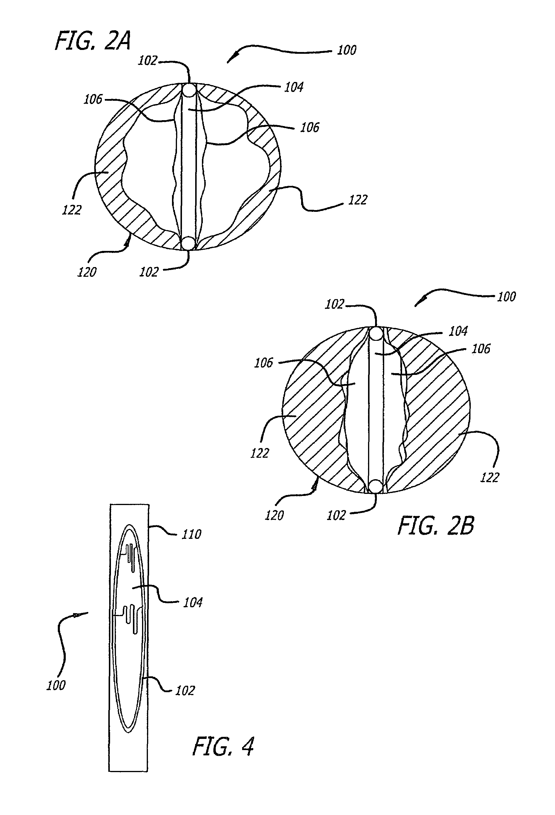
[0089]The present invention seeks to reduce the amount of blood that flows into the left atrium from the left ventricle during the systole phase of heart contraction. Most instances of this mitral valve regurgitation are caused by poor coaptation of the mitral valve leaflets that create openings between these leaflets when the mitral valve is closed. The present invention decreases the size of these opening between the mitral valve leaflets, and in some cases completely eliminates the openings, allowing the mitral valve to function with little or no regurgitation. This is achieved in at least some of the example embodiments described in this specification by positioning a member between the two mitral valve leaflets to close or fill up the openings between the leaflets when closed.

[0090]FIGS. 1A-4

[0091]One such design can be seen in FIGS. 1A-4 which illustrates a preferred embodiment of a prosthesis 100 according to the present invention. The prosthesis 100 includes a pocket 106 for...


PUM


Abstract

In one embodiment, the present invention provides a prosthesis that can be implanted within a heart to at least partially block gaps that may be present between the two mitral valve leaflets. In one preferred embodiment, the prosthesis includes an anchoring ring that expands within the left atrium to anchor the prosthesis and a pocket member fixed to the anchoring ring. The pocket member is positioned within the mitral valve, between the leaflets so that an open end of the pocket member is positioned within the left ventricle. When the mitral valve is open, blood flows past the pocket member, maintaining the pocket member in a collapsed state. When the mitral valve closes, the backpressure of the blood pushes into the pocket member, expanding the pocket member to an inflated shape. The mitral valve leaflets contact the expanded pocket member, allowing the prosthesis to block at least a portion of the openings between the leaflets, thereby minimizing regurgitated blood flow into the left atrium.

Description

RELATED APPLICATIONS[0001]This application claims priority to U.S. Provisional Application Ser. No. 60 / 609,345 filed Sep. 14, 2004 entitled Device and Method for Reducing Mitral Valve Regurgitation; and U.S. Provisional Application Ser. No. 60 / 657,919 filed Mar. 3, 2005 entitled Device and Method for Reducing Mitral Valve Regurgitation; both of which are hereby incorporated by reference.BACKGROUND OF THE INVENTION[0002]The mitral valve is one of the most crucial of the four valves of the human heart, preventing the regurgitation of blood from the left ventricle into the left atrium during contraction of the heart. Located between the left atrium and the left ventricle, the mitral valve includes two leaflets positioned to block blood flow in a closed state while allowing blood flow in an opened state.[0003]The mitral valve is opened and closed by a pressure differential between the left atrium and left ventricle and by a complex network of collagenous cord-like structures called chor...

Claims


Application Information

Patent Timeline
Patent Type & Authority Patents(United States)
IPC IPC(8): A61F2/24
CPCA61B17/00234A61F2/246A61B17/12013A61B2017/00867A61F2/2412A61B2017/00783A61F2210/0014A61F2210/0061A61F2210/0066A61F2/2466
Inventor ZAKAY, AVRAHAMROTTENBERG, DANMISHALY, DAVIDALON, DAVID
Owner EDWARDS LIFESCIENCES AG
Learn More