Registered jack with enhanced EMI protection

a registered jack and enhanced technology, applied in the direction of coupling device connection, coupling protective earth/shielding arrangement, two-part coupling device, etc., can solve the problems of reducing affecting the effective performance of the circuit, and prone to electromagnetic interference (emi) in registered jacks. , to achieve the effect of improving the emi shielding

Active Publication Date: 2010-04-27
AMPHENOL CORP
View PDF36 Cites 14 Cited by
  • Summary
  • Abstract
  • Description
  • Claims
  • Application Information

AI Technical Summary

Benefits of technology

[0008]To achieve the above and other objects, the present invention is directed to an electrical connector having a shield. The top of the shield has two rows of tabs; two flaps, one on either side of the shield; and a tab on the bottom. The flaps have mounting holes. When the connector is attached to a mounting panel, screws are driven through the holes in the flaps and corresponding holes in the mounting panel to secure the connector. The bottom tab and the two rows of top tabs electrically connect the shield to the mounting panel to provide extra EMI protection to the connector. The flaps provide yet another connection to provide EMI protection. The two rows of tabs can be positioned and sized such that the rear row of tabs engages with a flange in the rear of the top of the mounting panel.

Problems solved by technology

Registered jacks, like electrical and electronic equipment in general, are susceptible to electromagnetic interference (EMI), which is a (usually undesirable) disturbance that affects an electrical circuit due to electromagnetic radiation emitted from an external source.
The disturbance may interrupt, obstruct, or otherwise degrade or limit the effective performance of the circuit.

Method used


Image

  • Registered jack with enhanced EMI protection
  • Registered jack with enhanced EMI protection
  • Registered jack with enhanced EMI protection

Examples


Embodiment Construction

[0014]A preferred embodiment of the present invention will be set forth in detail with reference to the drawings, in which like reference numerals refer to like elements or steps throughout.

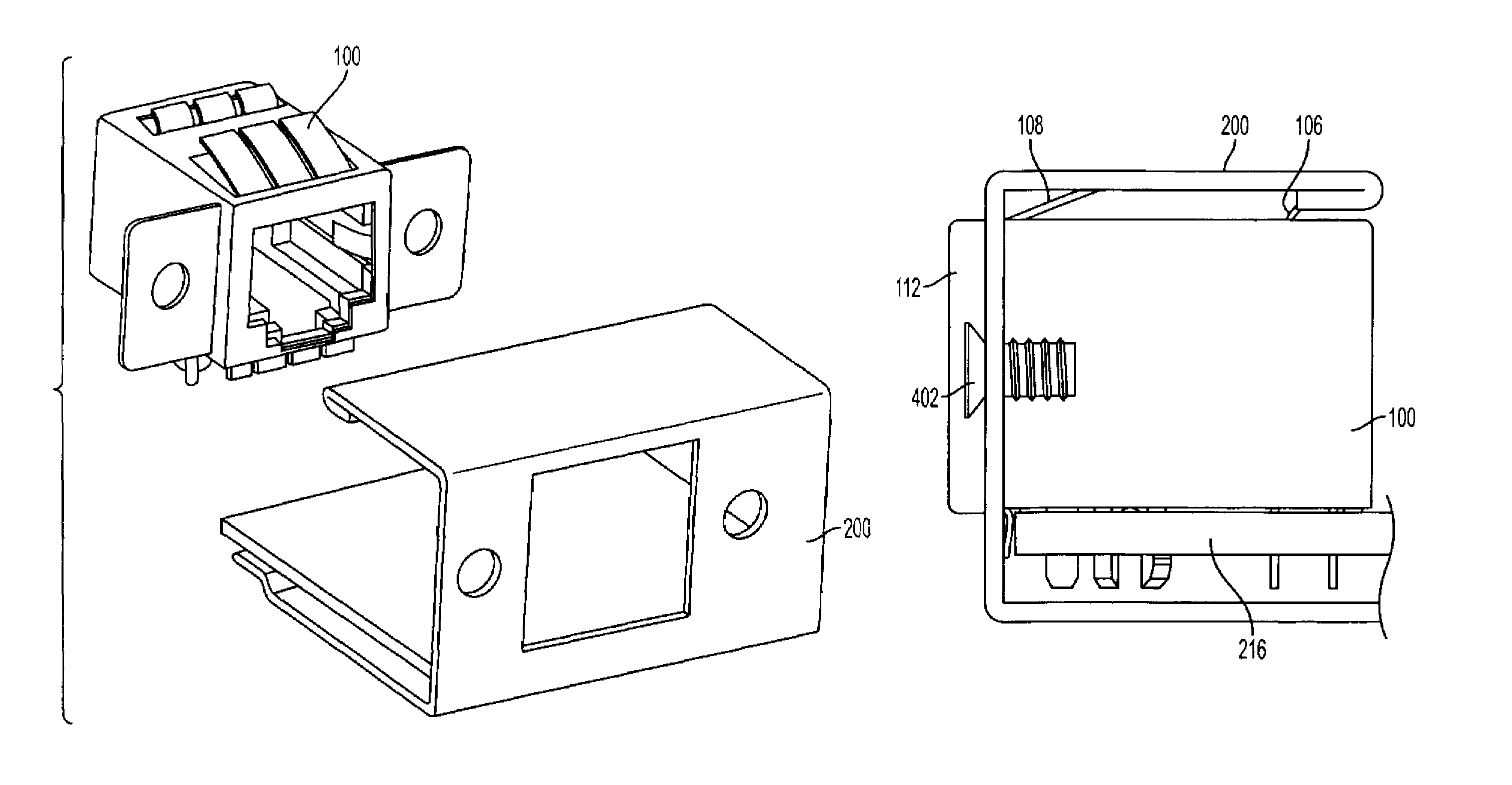
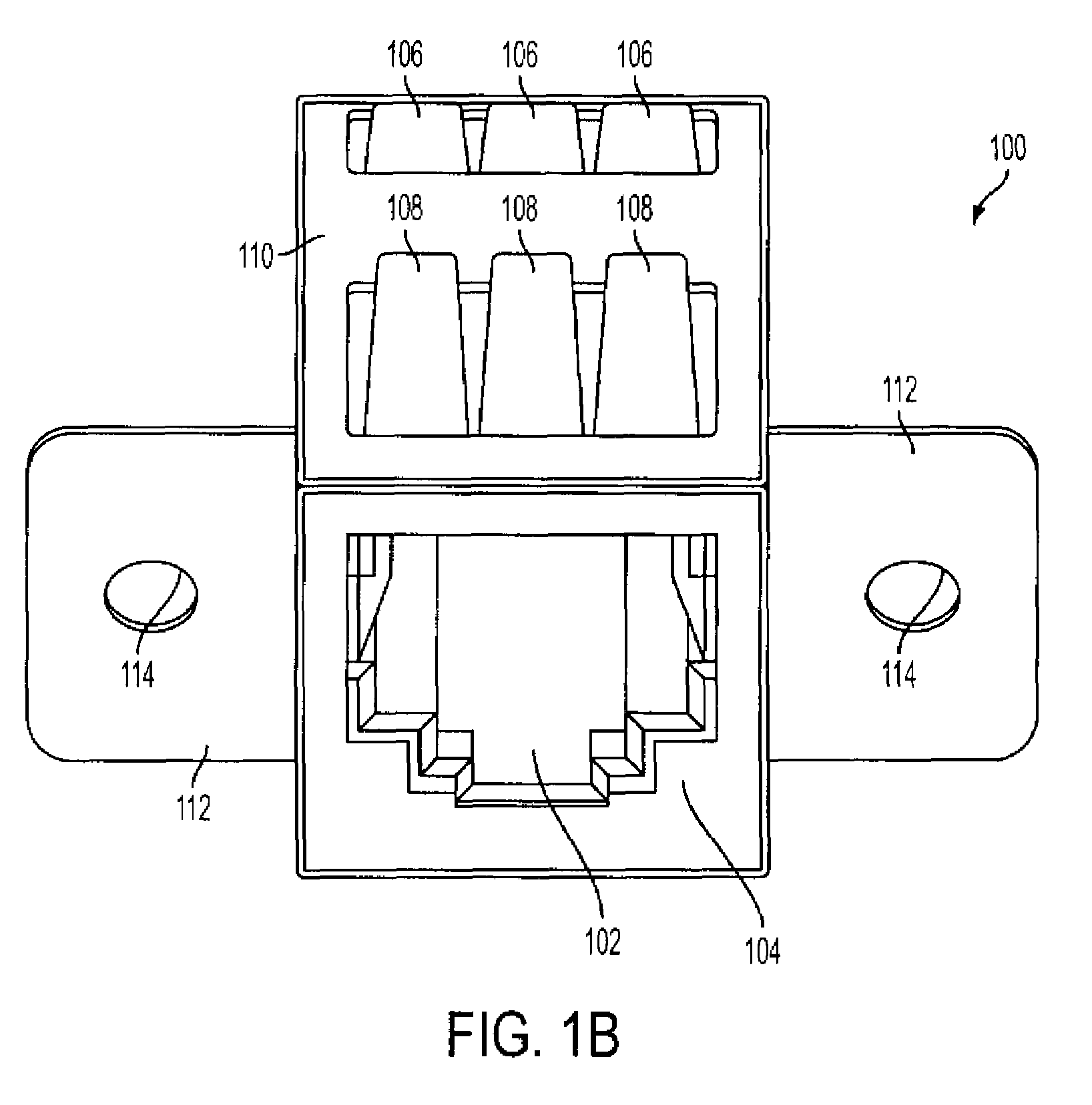
[0015]FIGS. 1A-1C show three perspective views of electrical connector 100 according to the preferred embodiment. The connector has a connector body 102 made of plastic or another dielectric material enclosed in a conductive shield 104, preferably formed of metal. Two rows of tabs 106, 108 are formed from the top 110 of the shield 104. The shield 104 has two flaps 112, each with a hole 114 to be used as explained below, extending from the sides 116 of the shield 104. The lower edge 118 of the front 120 of the shield 104 has tabs 122 extending down therefrom.

[0016]Preferably, the connector body 102 is formed of an engineering thermoplastic. The shield 104 is preferably formed of a copper alloy plated with nickel, with the tabs 122 dipped in pure tin. However, other non-conductive materials can be ...


PUM


Abstract

An electrical connector has a shield for EMI shielding. The top of the shield has two rows of tabs; two flaps, one on either side of the shield; and a tab on the bottom. The flaps have mounting holes. When the connector is attached to a mounting panel, screws or rivets are mounted through the holes in the flaps and corresponding holes in the mounting panel to secure the connector. The bottom tab and the two rows of top tabs electrically connect the shield to the mounting panel to provide extra EMI protection to the connector. The flaps provide yet another connection to provide EMI protection. The two rows of tabs can be positioned and sized such that the rear row of tabs engages with a flange in the rear of the top of the mounting panel. The electrical connector is preferably an RJ connector.

Description

FIELD OF THE INVENTION[0001]The present invention is directed to a registered jack (RJ) electrical connector and more specifically to an RJ connector having contacts to provide an electrical connection to a mounting frame to provide improved EMI protection.DESCRIPTION OF RELATED ART[0002]A registered jack (RJ) is a standardized physical interface for connecting telecommunications equipment (commonly, a telephone jack) or computer networking equipment. The standard designs for these connectors and their wiring are named RJ11, RJ14, RJ45, etc. These interface standards are most commonly used in North America, though some interfaces are used world-wide.[0003]An RJ connector is typically configured to receive a plug that is formed generally as a rectangular solid, with contacts on one side and a latch on the opposite side, the latch being formed integrally with the rectangular solid out of a deformable plastic. The jack has contacts to connect with those in the plug and a slot adapted t...

Claims


Application Information

Patent Timeline
Patent Type & Authority Patents(United States)
IPC IPC(8): H01R13/648
CPCH01R23/6873H01R13/748H01R13/65802H01R13/6582Y10S439/939
Inventor LAMBIE, KENTOUYANG, JEFF
Owner AMPHENOL CORP
Why Eureka
Try Eureka