
Wound dressing with vacuum reservoir

a vacuum reservoir and wound dressing technology, applied in the field of wound dressings with vacuum reservoirs, can solve the problems of difficult closure, less able to close the wound naturally, less able to successfully close the wound, etc., and achieve the effect of stimulating wound healing and facilitating fluid removal

Inactive Publication Date: 2010-04-20
SMITH & NEPHEW INC
View PDF124 Cites 282 Cited by
  • Summary
  • Abstract
  • Description
  • Claims
  • Application Information

AI Technical Summary

Benefits of technology

"The patent describes a wound dressing apparatus that includes a wound dressing member with a vacuum reservoir for applying subatmospheric pressure to remove fluid from the wound bed and promote healing. The apparatus also includes an access door and a visual pressure indicator to indicate the level of pressure within the vacuum reservoir. The lower absorbent member may contain medicament, antimicrobial agents, or other substances to promote healing, and the upper member may include a foam, nonwoven composite fabric, or other material. The apparatus may also include a vacuum source and a position sensor to actuate the visual alarm means when the pressure indicator detects a certain level of pressure. The technical effects of this invention include improved wound healing, reduced fluid accumulation, and improved vacuum pressure control."

Problems solved by technology

Unfortunately, closure is difficult with large wounds or wounds that have become infected.
Without sufficient blood flow, the epithelial and subcutaneous tissues surrounding the wound not only receive diminished oxygen and nutrients, but, are also less able to successfully fight microbial infection and, thus, are less able to close the wound naturally.
Such wounds have presented difficulties to medical personnel for many years.

Method used


Image

  • Wound dressing with vacuum reservoir
  • Wound dressing with vacuum reservoir
  • Wound dressing with vacuum reservoir

Examples


Embodiment Construction

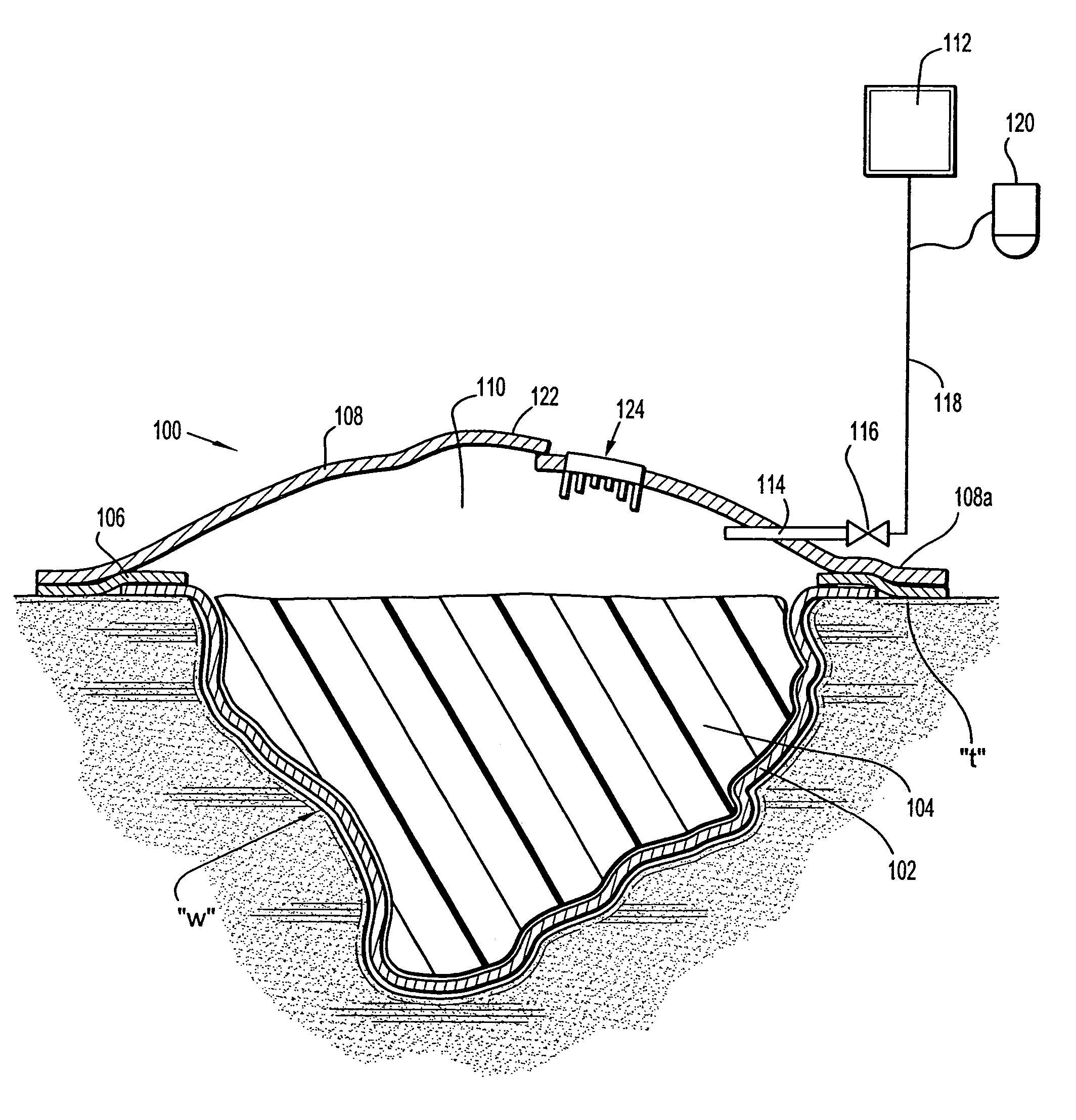
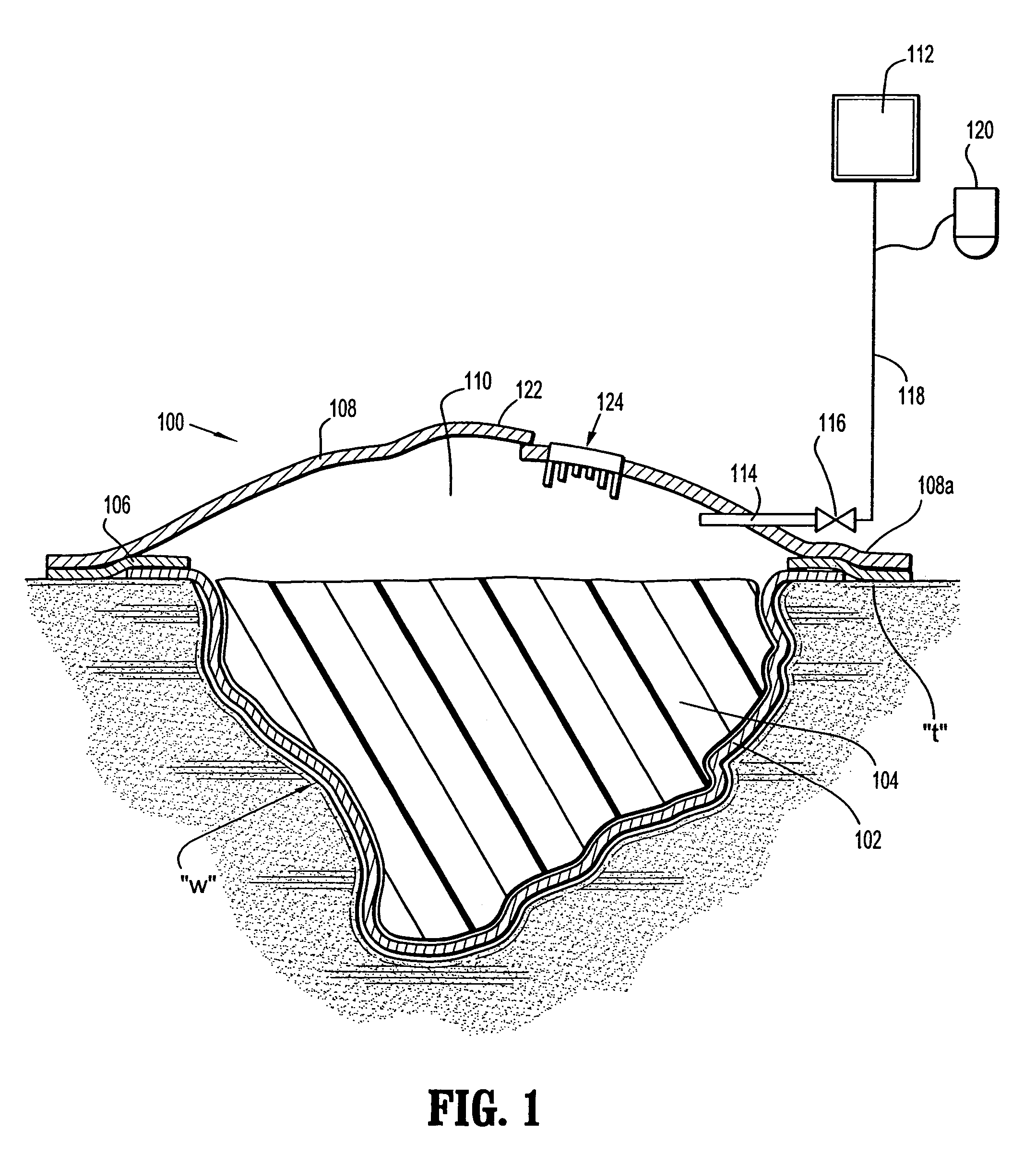
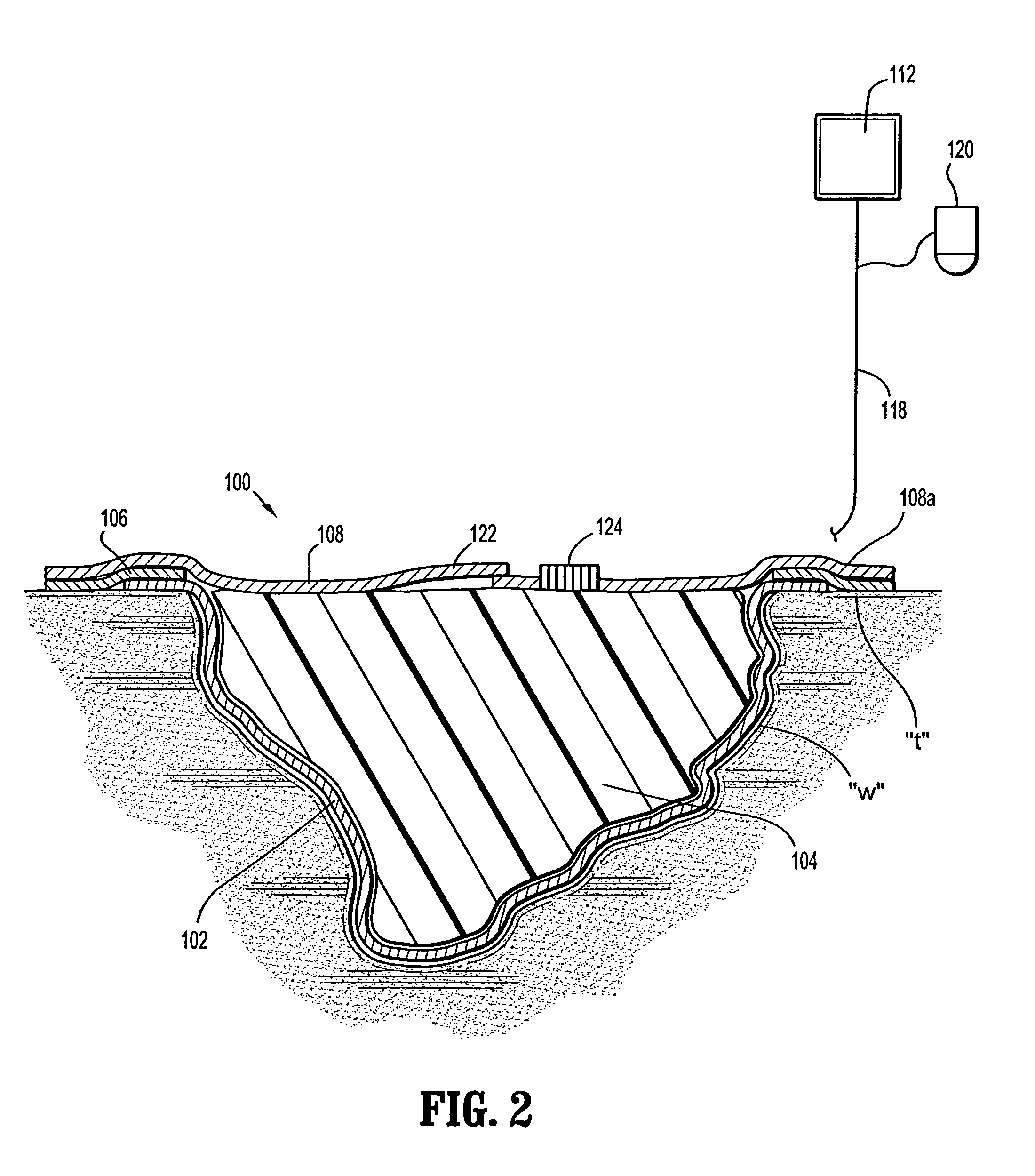
[0025]The composite wound dressing of the present disclosure promotes healing of a wound via the use of a vacuum reservoir. The vacuum reservoir subjects the wound to vacuum or subatmospheric pressure to effectively draw wound fluid including liquid exudates from the wound bed without the continuous use of a vacuum source or pump. Hence, vacuum pressure can be applied once or in varying intervals depending on the nature and severity of the wound until the composite wound dressing is saturated with exudate or the wound is healed. If the wound dressing is saturated with exudate and the wound is not healed, certain and / or all layers of the composite wound dressing can be replaced and the process of applying subatmospheric pressure can be repeated.

[0026]Referring now to FIGS. 1-3, the composite wound dressing 100 in accordance with a preferred embodiment of the present disclosure is illustrated in the form of an article with multiple layers arranged in juxtaposed or superposed relation....


PUM


Abstract

A wound dressing apparatus includes a wound dressing member dimensioned for positioning relative to a wound bed. The wound dressing member including an internal vacuum reservoir and has a port in communication with the vacuum reservoir for applying subatmospheric pressure to the vacuum reservoir to facilitate removal of fluid from the wound bed. The wound dressing member includes a visual pressure indicator associated therewith for indicating a level of pressure within the vacuum reservoir. The visual pressure indicator includes color indicia having a plurality of colors corresponding to a condition of the pressure within the vacuum reservoir. The wound dressing member includes a lower absorbent member positionable adjacent the wound bed and an upper member which at least partially defines the vacuum reservoir. At least one of the top member and the lower absorbent member has the visual pressure indicator mounted thereto. The preferred visual pressure indicator includes an electronic position sensor. The visual pressure indicator further includes circuit means and visible alarm means. The circuit means is adapted to actuate the visible alarm means when the position sensor detects a relative positioning of the top member of the wound dressing member to provide a visual indication of the condition of the subatmospheric pressure within the vacuum reservoir.

Description

CROSS-REFERENCE TO RELATED APPLICATIONS[0001]This patent application claims priority to and the benefit of U.S. Provisional Patent Application No. 60 / 714,805, filed in the U.S. Patent and Trademark Office on Sep. 7, 2005.BACKGROUND[0002]1. Technical Field[0003]The present disclosure relates to an apparatus for treating an open wound, and, more specifically, relates to a wound dressing that draws wound fluids into a vacuum reservoir to facilitate the wound healing process.[0004]2. Description of Related Art[0005]Wound closure involves the migration of epithelial and subcutaneous tissue adjacent the wound towards the center of the wound until the wound closes. Unfortunately, closure is difficult with large wounds or wounds that have become infected. In such wounds, a zone of stasis (i.e. an area in which localized swelling of tissue restricts the flow of blood to the tissues) forms near the surface of the wound. Without sufficient blood flow, the epithelial and subcutaneous tissues su...

Claims


Application Information

Patent Timeline
Patent Type & Authority Patents(United States)
IPC IPC(8): A61M1/00
CPCA61M1/0031A61M1/0088A61F13/0216A61M1/0027A61F13/00068A61M27/00A61M2205/15A61M2205/18A61M2205/583A61M2205/587A61M2205/6081A61M2205/3344A61M1/732A61M1/74A61M1/966A61M1/985A61M1/915A61M1/984A61F13/0209A61F13/05A61F13/00063A61M39/24A61M2205/3368A61M2205/584A61M2205/8206
Inventor HAGGSTROM, KURTFINK, DAVIDGRUNDMEIER, KATJA
Owner SMITH & NEPHEW INC
Learn More