
Force redistributing system for a vehicle in the event of a rear impact

a technology of force distribution system and rear impact, which is applied in the direction of roof, vehicle arrangement, transportation and packaging, etc., can solve the problems of rear impact affecting the vehicle fuel system, affecting the stability of the rear floor and third row seat, and the wedin apparatus not protecting against door opening closur

Inactive Publication Date: 2010-04-20
FCA US
View PDF56 Cites 20 Cited by
  • Summary
  • Abstract
  • Description
  • Claims
  • Application Information

AI Technical Summary

Problems solved by technology

The U.S. Pat. No. 4,090,721 impact specifications require the rear portion of a vehicle aft of the end of the rear axle system 110 to crush, which upsets the rear floor and third row seat stability.
Rear impacts can also affect the vehicle fuel system and displace a spare tire stored under the vehicle body.
The Wedin apparatus does not protect against door opening closure, and it does not stabilize the rear floor of an impacted vehicle.
The Wedin apparatus does not provide force distribution of off-center rear impacts.

Method used


Image

  • Force redistributing system for a vehicle in the event of a rear impact
  • Force redistributing system for a vehicle in the event of a rear impact
  • Force redistributing system for a vehicle in the event of a rear impact

Examples


Embodiment Construction

[0018]In the following description, several well-known features of a vehicle underbody, a vehicle exterior body, an exhaust system, a fuel system and a rear chassis and rear axle system are not shown or described so as not to obscure the present invention.

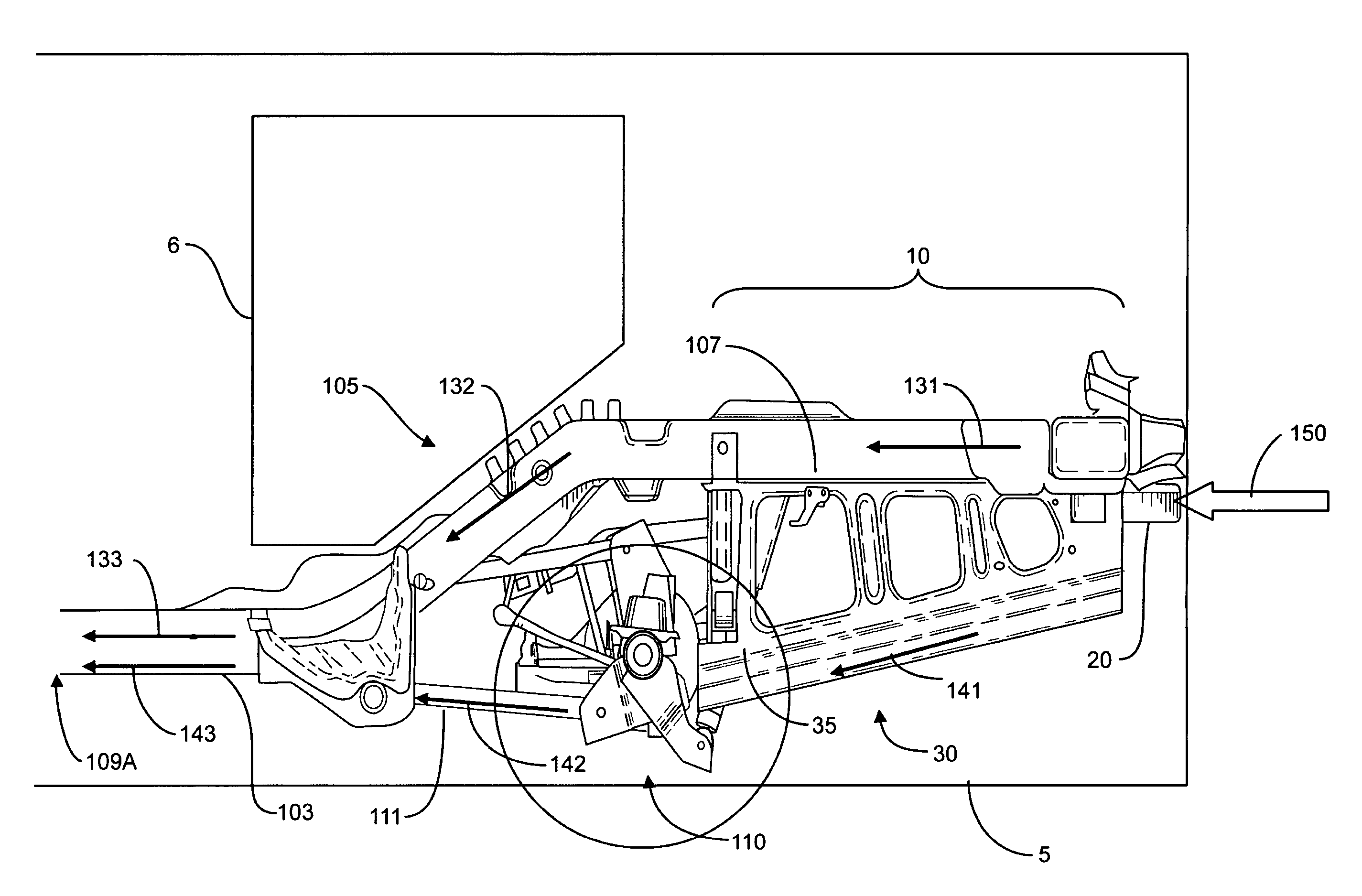
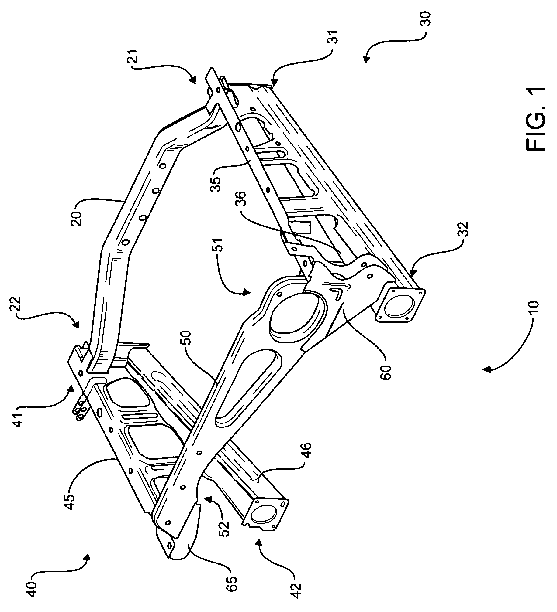
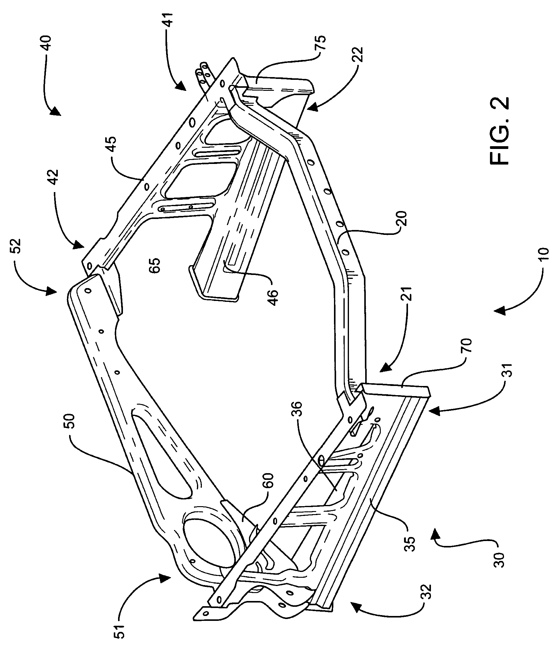
[0019]Referring now to the drawings, FIGS. 1 and 2 illustrate a first and a second isometric view, respectively, of an exemplary embodiment of an apparatus 10 of the force redistributing system 9 (FIG. 3) in accordance with the present invention. FIG. 1 illustrates a front isometric view and FIG. 2 illustrates a rear isometric view of the apparatus 10 of the force redistributing system 9. The force redistributing system 9 includes rear rails of an underbody of a vehicle 5 (FIGS. 3 and 4) having an exterior body. Throughout this document the terms force and load are used interchangeably.

[0020]The apparatus 10 includes a first cross-car member 20, a first side load distributor 30, a second side load distributor 40, and a second cross...


PUM


Abstract

A force redistributing system operably attached to a vehicle. The system includes a first cross-car member, a first side load distributor and a second side load distributor. The first and second side load distributors are parallel to and spaced apart from each other and are attached at respective first ends to opposing ends of the first cross-car member. The system includes a second cross-car member having opposing ends, which are attached to second ends of the first and second side load distributors. The system establishes cross vehicle loading of force from a rear impact wherein the force from the rear impact on the vehicle is transferred along an upper path and a lower path.

Description

FIELD OF THE INVENTION[0001]This invention relates generally to a system to redistribute force from a rear impact on a vehicle. In particular, the invention relates to transferring the energy from a rear impact on a vehicle along a lower path and an upper path in the vehicle.BACKGROUND OF THE INVENTION[0002]Mobile vehicles are typically equipped with rear bumper systems to absorb the force from rear end impacts. Some of the force is transferred from the bumpers to the rails of the underbody in the vehicle. When the rear impact is non-symmetric, the force is unevenly distributed between the sides of the vehicles. Offset loading of the impact force occurs when the impact is not centered on the rear bumper. Symmetric loading of the impact force occurs when the impact is centered on the rear bumper.[0003]The U.S. Pat. No. 4,090,721 impact specifications require the rear portion of a vehicle aft of the end of the rear axle system 110 to crush, which upsets the rear floor and third row se...

Claims


Application Information

Patent Timeline
Patent Type & Authority Patents(United States)
IPC IPC(8): B62D21/00
CPCB62D21/152
Inventor WEHNER, TIMOTHY JTHELEN, TEDSKILTON, DAVECOWING, THOMASKAPADIA, APURVA N
Owner FCA US
Learn More