
Noise reducing fluid passageways for fluid control devices

a fluid flow control and fluid passageway technology, applied in fluid dynamics, lighting and heating apparatus, transportation and packaging, etc., can solve the problems of vibration and noise, noise is undesirable or unacceptable characteristic of fluid flow control devices, etc., and achieve the effect of reducing transmitted nois

Active Publication Date: 2010-04-06
FLOWSERVE PTE LTD
View PDF66 Cites 14 Cited by
  • Summary
  • Abstract
  • Description
  • Claims
  • Application Information

AI Technical Summary

Benefits of technology

The present invention provides a cost-effective way to improve pressure reducing components in a fluid flow control device to reduce transmitted noise. One embodiment involves a trim disk assembly with two disks that have voids in them that create an expansion / contraction mechanism for the fluid passageway. Another embodiment involves a device with multiple fluid passageways that have cross-sectional areas with at least two abutting, offset shapes. These features help to reduce noise and improve the performance of fluid flow control devices.

Problems solved by technology

These pressure and velocity fluctuations cause vibrations and noise.
In many applications, noise is an undesirable or unacceptable characteristic of a fluid flow control device.

Method used


Image

  • Noise reducing fluid passageways for fluid control devices
  • Noise reducing fluid passageways for fluid control devices
  • Noise reducing fluid passageways for fluid control devices

Examples


Embodiment Construction

[0024]Although the foregoing description contains many specifics, these should not be construed as limiting the scope of the present invention, but merely as providing illustrations of some representative embodiments. Similarly, other embodiments of the invention may be devised that do not depart from the spirit or scope of the present invention. Features from different embodiments may be employed in combination. The scope of the invention is, therefore, indicated and limited only by the appended claims and their legal equivalents, rather than by the foregoing description. All additions, deletions, and modifications to the invention, as disclosed herein, which fall within the meaning and scope of the claims, are to be embraced thereby.

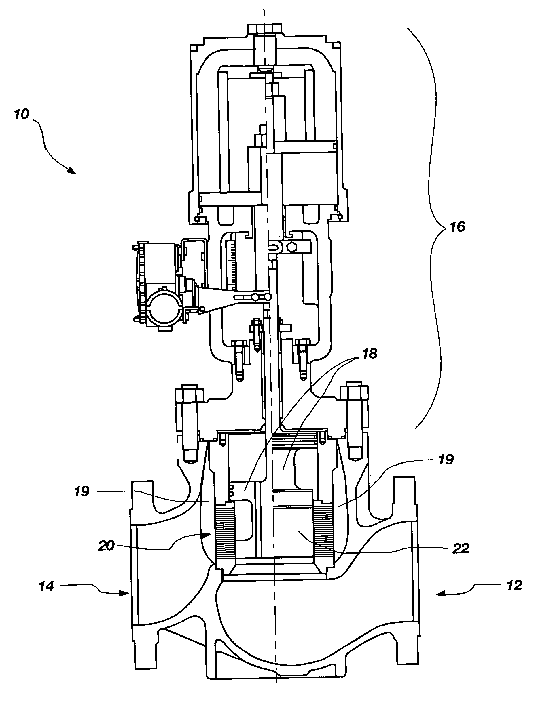
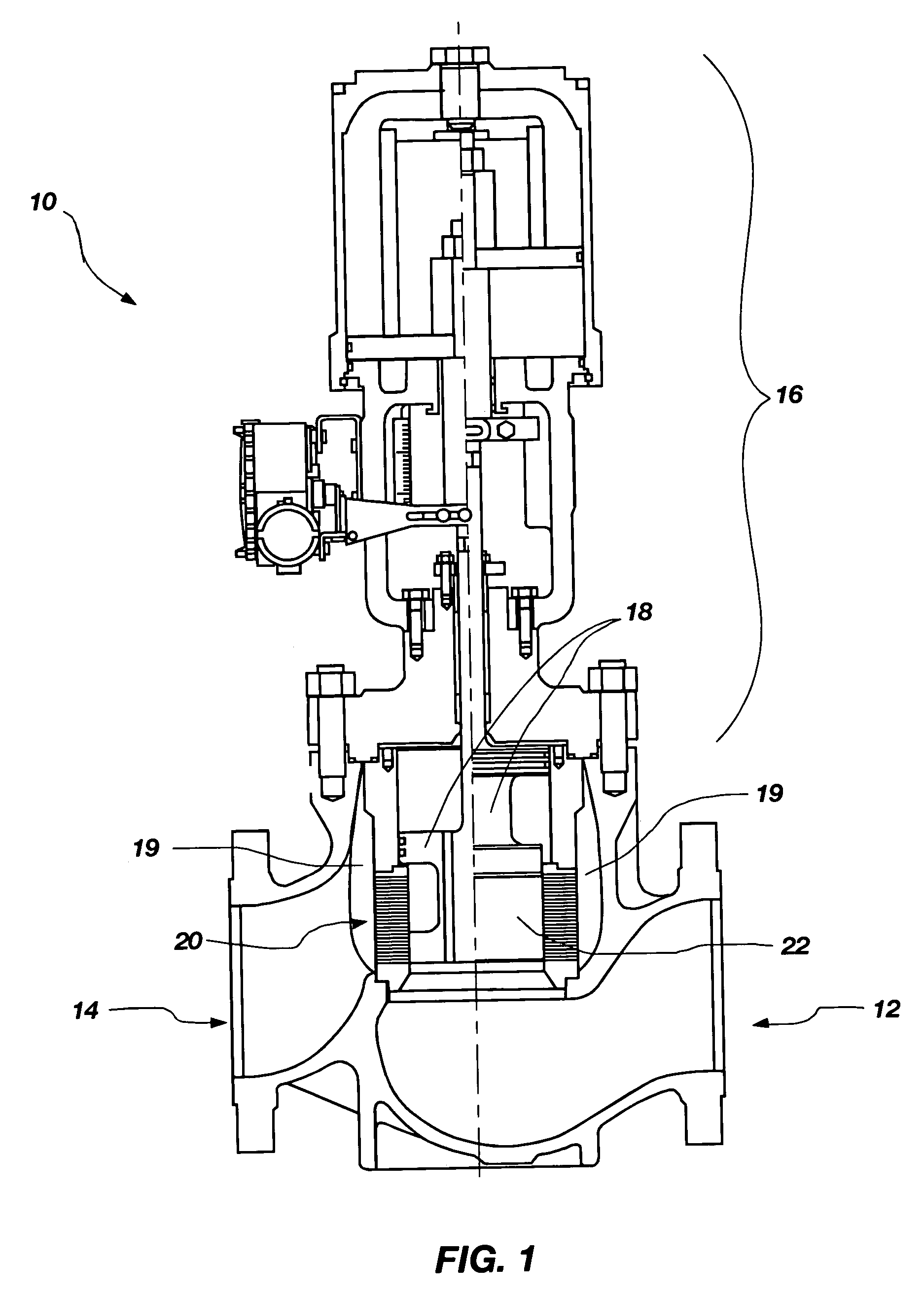
[0025]FIG. 1 is a vertical cross section of a representative fluid flow control device 10 that embodies teachings of the present invention. The fluid flow control device 10 includes a fluid inlet 12, a fluid outlet 14, and a trim disk assembly 20. Furt...


PUM


Abstract

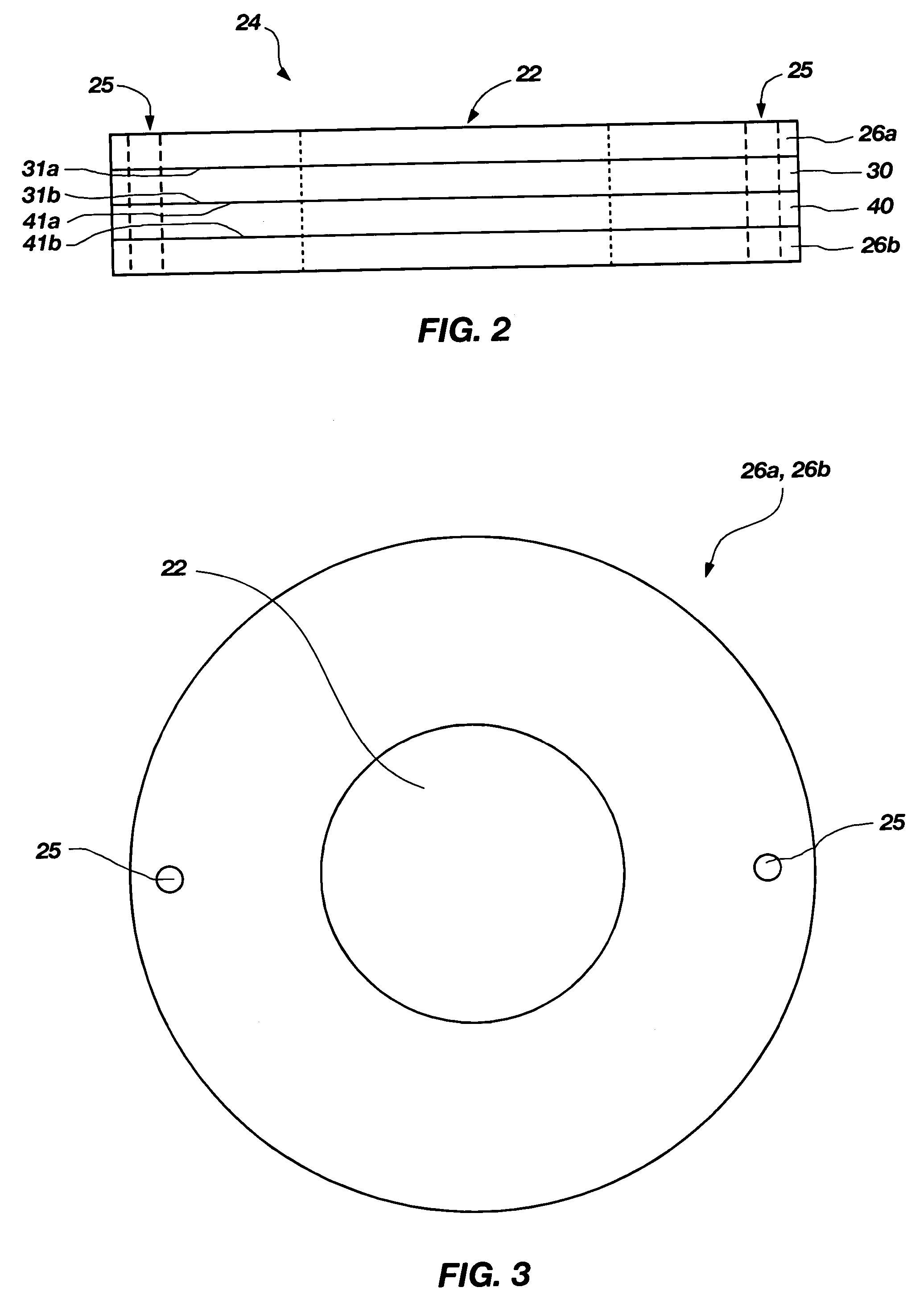
Trim disk assemblies for use in fluid flow control devices include a first disk and a second disk. An elongated void is formed in a surface of each of the first disk and the second disk. The second disk is aligned with the first disk to provide fluid communication between the void of the first disk and the void of the second disk, the void of the first disk being offset or staggered from the void of the second disk. The void of the first disk and the void of the second disk at least partially define a fluid passageway having a cross-sectional area characterized by increases and decreases in cross-sectional area, which define an expansion / contraction mechanism of the fluid passageway.

Description

CROSS-REFERENCE TO RELATED APPLICATIONS[0001]This application claims the benefit of provisional Application No. 60 / 657,225, which was filed Feb. 28, 2005, and entitled Noise Reducing Fluid Passageways For Fluid Flow Control Devices.FIELD OF THE INVENTION[0002]The present invention relates to fluid flow control devices and, more specifically, to an improved noise reduction mechanism for a fluid flow control device. The present invention also relates to trim disk assemblies for use in such fluid flow control devices.BACKGROUND OF THE INVENTION[0003]In many areas of industry, it is often necessary to reduce the pressure of fluids (both liquids and gases) within a pipeline. Fluid flow control valve systems are often used for this purpose. Various designs for fluid flow control valves have been presented in the art. For example, a plurality of tortuous fluid flow paths may be provided within a fluid flow control valve. As fluid passes through the tortuous fluid flow paths, the fluid is c...

Claims


Application Information

Patent Timeline
Patent Type & Authority Patents(United States)
IPC IPC(8): F15D1/02F16K47/08
CPCF16K47/08Y10T137/86734Y10T137/87265Y10T137/86759
Inventor HAINES, BRADFORD
Owner FLOWSERVE PTE LTD
Learn More