Vane pump

a technology of vane pump and vacuum pump, which is applied in the field of vane pump, can solve the problems of affecting the degree of product evacuation neither purposefully, and affecting the uniformity of discharge, so as to achieve the effect of optimising function and reducing the length of sealing area

Active Publication Date: 2010-03-23
ALBERT HANDTMANN MASCHFABRICK
View PDF18 Cites 4 Cited by
  • Summary
  • Abstract
  • Description
  • Claims
  • Application Information

AI Technical Summary

Benefits of technology

[0008]Starting from this situation, the object underlying the present disclosure is to provide a vane pump having an exact discharge and thus portioning accuracy, and which moreover permits prolonged service life.
[0009]By at least one sealing element for sealing a gap between the rotor and the wall of the pump case being provided in the sealing area, the sealing function between the pressure and suction areas can be improved. Apart from the sealing property, the sealing element furthermore has the advantage of stripping off the mass entrained at the circumferential surfaces of the rotor, so that it can not be further transported towards the suction area. It can thus be also prevented that entrained mass can possibly penetrate the vacuum extension. The sealing function here no longer depends on the geometry as well as the existing tolerances of the delivery mechanism parts. Even in case of high pressures in the pressure area, an adequate sealing is provided. The leakage flows can be reduced and thus the accuracy of the discharge or the portioning accuracy of the pump can also be increased with very different operational conditions. Due to the sealing element, the possible maximum pressure difference between pressure and suction areas can be maintained.
[0010]Advantageously, the sealing element is formed of a softer and / or more elastic material than the case, the vane and the rotor, so that a perfect sealing function is provided and the sealing element serves as inexpensive expendable part.

Problems solved by technology

In addition, wear and different performance characteristics, such as delivery pressure, product consistency, etc. have a disadvantageous effect on the uniformity of discharge.
Meat deposits in the area of the vacuum extension or in the vacuum channel to the vacuum pump, respectively, can lead to a clogging of the channel or to a damage of the vacuum pump.
Due to the gap width problem, the degree of the evacuation of the product can neither be purposefully influenced.
With increasing wear and thus decreasing sealing function, expensive delivery mechanism parts have to be replaced, such as rotor, pump case, pump vane, etc., to ensure an adequate sealing function.

Method used


Image

  • Vane pump
  • Vane pump
  • Vane pump

Examples


Embodiment Construction

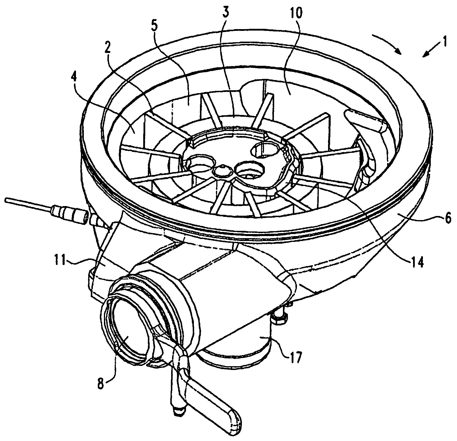
[0027]FIG. 3 shows the perspective structure of the vane pump 1 according to the present disclosure. As can be taken from FIG. 3, the vane pump for delivering pasty mass, in particular sausage meat, comprises a pump case 6 as well as an inlet 10 for the pasty mass and an outlet 8 for the portioned mass. The inlet 10 is, for example, connected with an outlet of a hopper, e.g. a vacuum hopper (not shown) via which the pasty mass is supplied to the vane pump 1. The outlet 8 is, for example, connected to a filling tube (not shown) of a filling machine. Via the filling tube, the portioned pasty mass is then pushed into the sausage casings in a known manner. In the pump case 6, the vane pump 1 comprises a preferably eccentrically arranged rotor 3 that can be rotated and is driven via a pump shaft 17 about the axis R (see FIG. 2). As can be seen in FIG. 2, the central axis R of the rotor is spaced from the central axis P of the case 6.

[0028]The rotor comprises vanes 2 held so as to be radi...


PUM


Abstract

A vane pump for delivering pasty masses, in particular sausage meat, with a pump case 6 and a rotatably held rotor 3 comprising vanes 2 held so as to be radially movable which form delivery cells 4 together with the wall 5 of the pump case 6, with a suction area, a pressure area and a sealing area separating the pressure area from the suction area. For a better sealing between the suction area and the sealing area, in particular in case of high pressures in the pressure area, and for increasing the service life of the vane pump, in the sealing area at least one sealing element is provided for sealing a gap between the rotor and the wall of the pump case.

Description

CROSS-REFERENCE TO RELATED APPLICATION[0001]The present application claims the benefit of priority of European Patent Application No. 06 006 166.0 filed on Mar. 24, 2006. The entire text of the priority application is incorporated herein by reference in its entirety.FIELD OF THE DISCLOSURE[0002]The disclosure relates to a vane pump, such as used in meat processing, such as sausage making operations.BACKGROUND OF THE DISCLOSURE[0003]Vane pumps are already being employed for delivering sausage meat from hoppers into filling tubes via which sausage casings are filled with the sausage meat. Such vane pumps are already described, for example, in the EP 0432388 B2 and the EP 1040758 A1. Vane pumps consist of a pump case and a rotor eccentrically arranged therein which can be caused to rotate. Vanes held so as to be radially movable are arranged in the rotor and form delivery cells together with the wall of the pump case, the bottom and the lid of the case and the outer surface of the roto...

Claims


Application Information

Patent Timeline
Patent Type & Authority Patents(United States)
IPC IPC(8): A22C11/08
CPCA22C11/08F04C13/002F04C15/0011
Inventor MAILE, BERNDMANTZ, PAULSTAUDENRAUSCH, MARTIN
Owner ALBERT HANDTMANN MASCHFABRICK
Why Eureka
Try Eureka