Printer having disengageably gear driven media pick-up roller
What is Al technical title?
Al technical title is built by PatSnap Al team. It summarizes the technical point description of the patent document.
a technology of media pick-up roller and gear drive, which is applied in the direction of belt/chain/gearing, thin material handling, article separation, etc., can solve the problems of speed mismatch on different parts of the sheet, reduce reduce drag on the media, and free wheeling reduces the occurrence of speed spikes.
Inactive Publication Date: 2010-03-23
SILVERBROOK RES PTY LTD +1
View PDF28 Cites 9 Cited by
Summary
Abstract
Description
Claims
Application Information
AI Technical Summary
This helps you quickly interpret patents by identifying the three key elements:
Problems solved by technology
Method used
Benefits of technology
[0009]The present invention provides a gear train for driving the pick-up roller in which one of the gears can be disengaged from the other gears, thereby allowing the pick-up roller to ‘free wheel’ upon delivery of the print media to the media transport mechanism. This free wheeling reduces the occurrence of speed spikes in the feed of the print media. Power efficiency and accurate delivery of the media is also enhanced by arranging the disengageble gear in the gear train as close to the pick-up roller as possible to reduce drag on the media by the free wheeling pick-up roller.
[0101]Optionally, the step of positioning the roller comprises positioning a plurality of elongate rollers so as to be supported at their longitudinal first ends by the support frame and positioned at their longitudinal second ends in a respective one of a plurality of second bearings of the second fixing plate, each second bearing being configured to allow rotation of the respective roller about the second end thereof; the step of positioning the first bearing of the first fixing plate comprises positioning a plurality of first bearings about the first end of each respective roller, each first bearing being configured to allow rotation of the respective roller about the first end thereof; and in the step of engaging the first fixing plate, the configuration of each of the bearings allows the pivoting of the respective elongate roller about the second end thereof.
[0149]in the engagement step, the configuration of each of the bearings allows the pivoting of the respective elongate shaft about the second end thereof.
Problems solved by technology
This is because, the transport mechanism generally pulls the sheets faster than the pick-up device can deliver the sheets, resulting in a speed mismatch on different parts of the sheet.
Method used
Image
Click on the blue label to locate the original text in one second.
Reading with bidirectional positioning of images and text.
Examples
Embodiment Construction
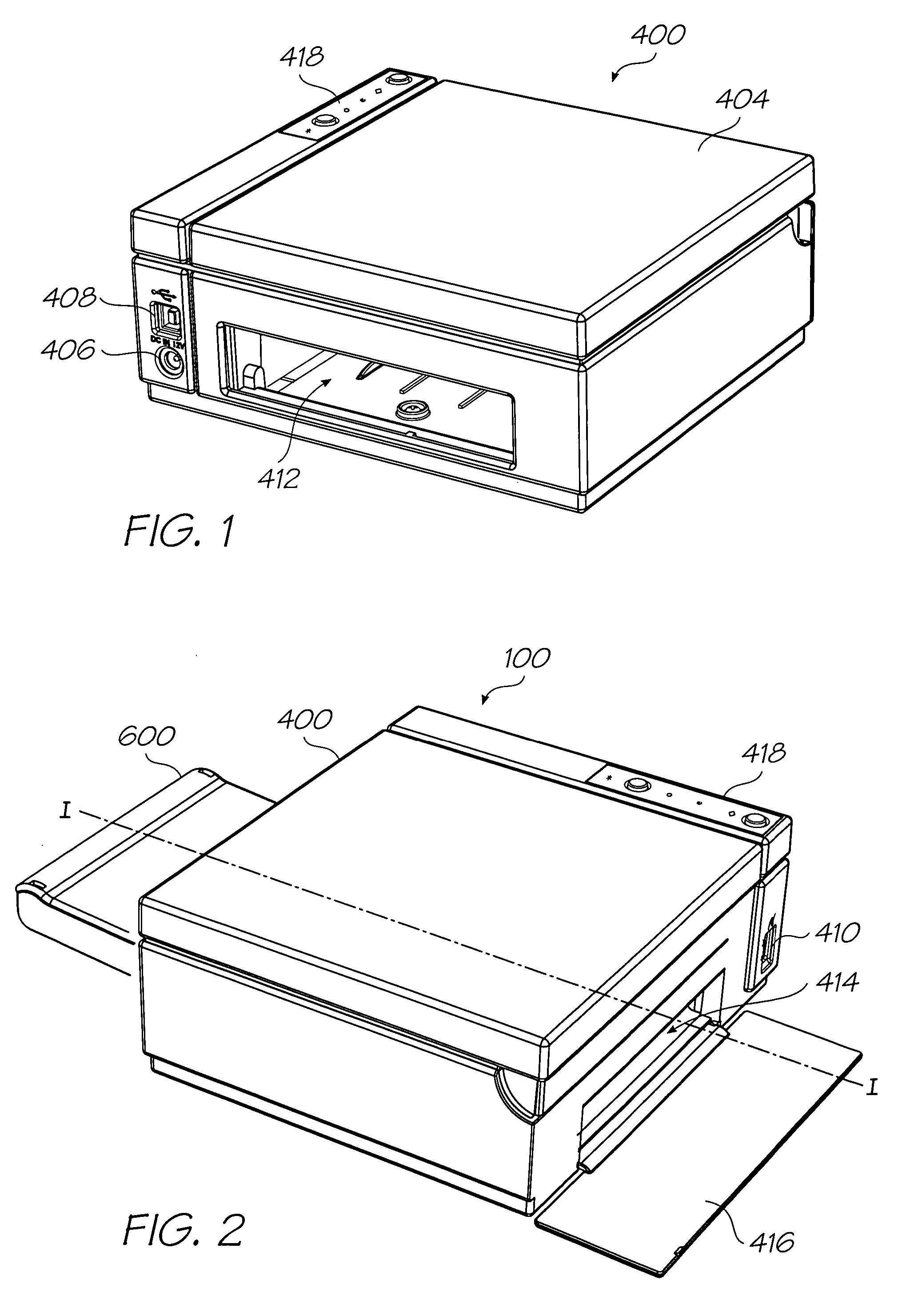
[0272]A printer 100 is variously illustrated in the accompanying drawings. The printer 100 is intended for use as a digital photo color printer and is dimensioned to print 100 millimeter by 150 millimeter (4 inch by 6 inch) photos whilst being compact in size and light in weight. As will become apparent from the following detailed description, reconfiguration and dimensioning of the printer could be carried out so as to provide for other printing purposes.
[0273]The printer 100 of the illustrated photo printer embodiment has dimensions of 18.6 cm (W); 7.6 cm (H); 16.3 cm (D), and a weight of less than two Kilograms. The compact and lightweight design of the printer provides portability and ease of use.
[0274]The printer 100 may be easily connected to a PC via a USB connector 408 (such as a USB 1.1 port for USB 2.0 compatible PCs) and to digital cameras and other digital photo equipment, such as electronic photo albums and cellular telephones, via USB or a PictBridge connector 410. Dir...
PUM
Abstract
A printer comprising: a sheet media transport mechanism for transporting sheet media past a printhead; a pick-up roller arranged to be rotated so as to contact and pick-up sheet media from a supply of sheet media and deliver the picked sheet media to the sheet media transport mechanism; and a gear assembly for communicating a driving force of a motor to the pick-up roller so as to rotate the pick-up roller, wherein a first gear of the gear assembly is arranged to disengage from a second gear of the gear assembly substantially at the point of delivery of a leading edge of the picked sheet media to the sheet media transport mechanism so as to cease communication of the driving force of the motor to the pick-up roller.
Description
FIELD OF THE INVENTION[0001]The present invention is related to a media pick-up device of a printer which is configured to accurately pick media from a media supply and deliver it to a media transport device of the printer.CO-PENDING APPLICATIONS[0002]The following applications have been filed by the Applicant simultaneously with the present application:[0003]11 / 293,80011 / 293,80211 / 293,80111 / 293,80811 / 293,80911 / 293,83211 / 293,83811 / 293,82511 / 293,84111 / 293,79911 / 293,79611 / 293,79711 / 293,79811 / 293,80411 / 293,84011 / 293,80311 / 293,83311 / 293,83411 / 293,83511 / 293,83611 / 293,83711 / 293,79211 / 293,79411 / 293,83911 / 293,82611 / 293,82911 / 293,83011 / 293,82711 / 293,8287,270,49411 / 293,82311 / 293,82411 / 293,83111 / 293,81511 / 293,81911 / 293,81811 / 293,81611 / 293,82011 / 293,81311 / 293,82211 / 293,81211 / 293,82111 / 293,81411 / 293,79311 / 293,84211 / 293,81111 / 293,80711 / 293,80611 / 293,80511 / 293,810[0004]The disclosures of these co-pending applications are incorporated herein by reference. The above applications have been identified...
Claims
Application Information
Patent Timeline
Application Date:The date an application was filed.
Publication Date:The date a patent or application was officially published.
First Publication Date:The earliest publication date of a patent with the same application number.
Issue Date:Publication date of the patent grant document.
PCT Entry Date:The Entry date of PCT National Phase.
Estimated Expiry Date:The statutory expiry date of a patent right according to the Patent Law, and it is the longest term of protection that the patent right can achieve without the termination of the patent right due to other reasons(Term extension factor has been taken into account ).
Invalid Date:Actual expiry date is based on effective date or publication date of legal transaction data of invalid patent.
Patent Type & Authority Patents(United States)
IPC IPC(8): B65H5/00
CPCB65H19/18B65H23/044Y10T74/19619Y10T74/19614
Inventor SILVERBROOK, KIAKING, TOBIN ALLENTOW, GREGORY MICHAELBERTOK, ATTILADYER, GEOFFREY PHILIPBRICE, ROBERT JOHNMACKEY, PAUL IANHIBBARD, CHRISTOPHER