
Lock for a USB connector

a technology for usb connectors and locks, applied in the field of locks, can solve the problems of complicated structure, high cost, and high software costs of conventional usb locks, and achieve the effect of simplifying the structur

Inactive Publication Date: 2010-03-16
JIN TAY IND CO LTD
View PDF15 Cites 67 Cited by
  • Summary
  • Abstract
  • Description
  • Claims
  • Application Information

AI Technical Summary

Benefits of technology

[0007]The main objective of the present invention is to provide a lock for a USB connector with simplified structure. The lock for a USB connector has a shell with an end opening, multiple lock assemblies mounted rotatably through the shell and an actuator mounted pivotally in the shell. Each lock assembly has a locking notch. The actuator has multiple locking protrusions selectively engaging the locking notches. The USB connector is inserted through the end opening into the shell and is selectively locked by a mounting segment on the actuator.

Problems solved by technology

To keep the information saved in the flash memory drive from being stolen, some software is developed but the software is usually expensive.
However, the conventional USB lock has complicated structures that are hard to manufacture and is cost much.

Method used


Image

  • Lock for a USB connector
  • Lock for a USB connector
  • Lock for a USB connector

Examples


Embodiment Construction

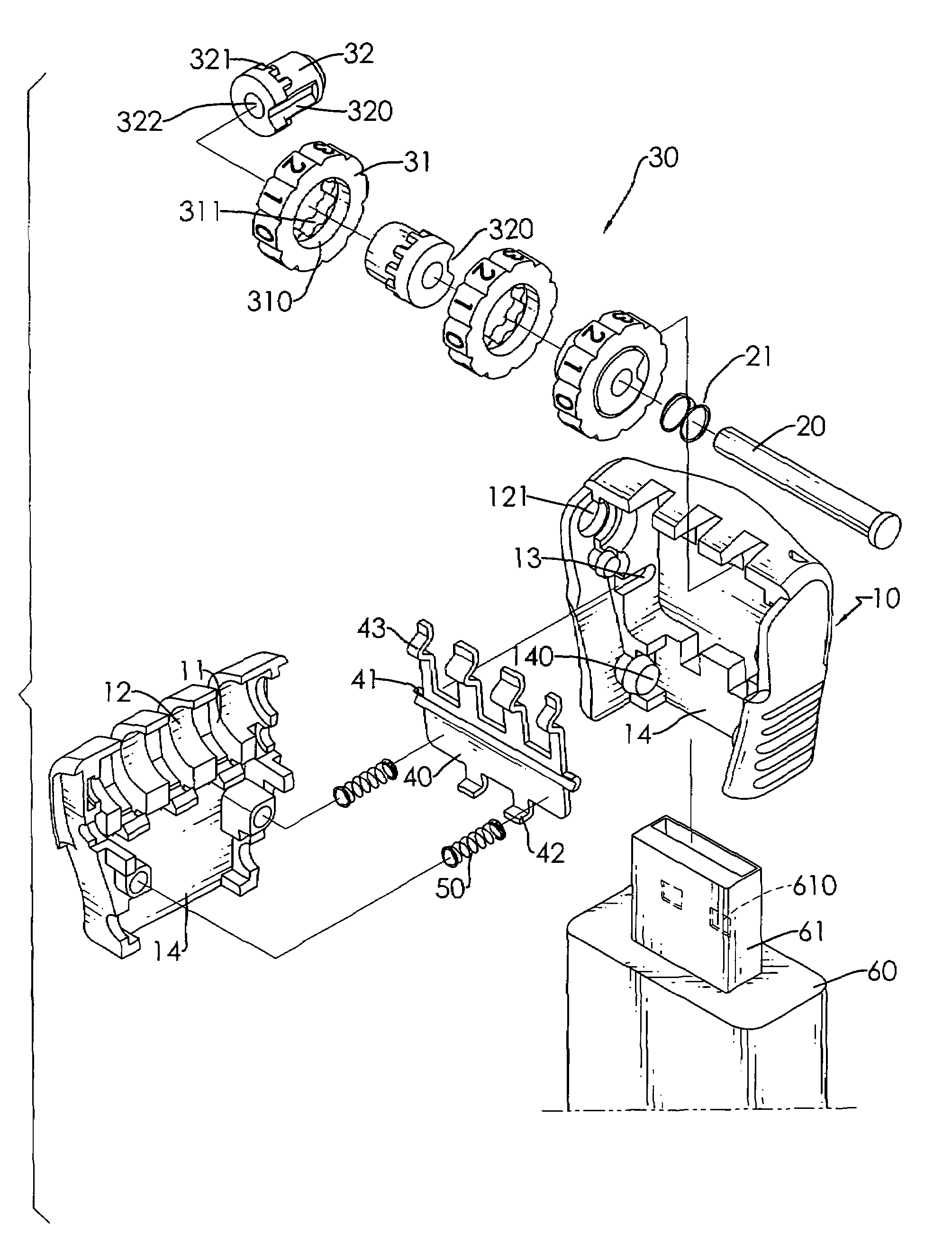
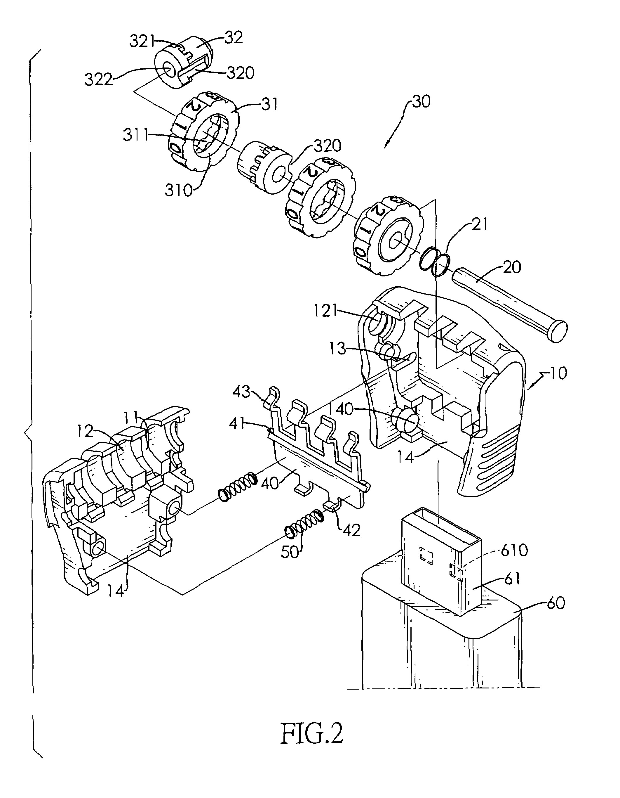
[0014]With reference to FIGS. 1 and 2, a lock for a USB connector in accordance with the present invention comprises a shell (10), multiple lock assemblies (30), a shaft (20), a retaining spring (21), an actuator (40) and at least one actuating spring (50).

[0015]The shell (10) is hollow, may comprise two half shells and has two inner sidewalls, a lock end, a mounting end, a transverse cavity (12), multiple mounting gaps (11), a side opening (121), two pivoting recesses (13), an end opening (14) and two limits (140). The mounting end is opposite to the lock end and is adjacent to the inner sidewalls. The transverse cavity (12) is adjacent to the lock end. The mounting gaps (11) are formed parallelly through the lock end and intersect and communicate with the transverse cavity (12). The side opening (121) is formed through one of the inner sidewalls and communicates with the transverse cavity (12). The pivoting recesses (13) are formed respectively in the inner sidewalls of the shell ...


PUM


Abstract

A lock for a USB connector has a shell with an end opening, multiple lock assemblies mounted rotatably through the shell and an actuator mounted pivotally in the shell. Each lock assembly has a locking notch. The actuator has multiple locking protrusions selectively engaging the locking notches. The USB connector is inserted through the end opening into the shell and is selectively locked by a mounting segment on the actuator.

Description

BACKGROUND OF THE INVENTION[0001]1. Field of the Invention[0002]The present invention relates to a lock, especially to a lock that is used to selectively lock a USB connector.[0003]2. Description of the Prior Arts[0004]USB connectors are widely used to connect peripheral devices to the computer. The connection compatibility was further improved by development automatic driver configuration software in operating systems, such as Microsoft Corporations, plug-and-play system for Windows. The automatic driver configuration software detects when a peripheral is connected using the USB port and automatically finds a corresponding driver for the peripheral. Therefore, the peripheral can be used after plugging into the computer through the USB port without manually installing any drivers. One of the widely used peripheral with USB connector is flash memory drive.[0005]To keep the information saved in the flash memory drive from being stolen, some software is developed but the software is us...

Claims


Application Information

Patent Timeline
Patent Type & Authority Patents(United States)
IPC IPC(8): E05B65/00
CPCE05B37/02H01R13/6397Y10T70/5009Y10T70/415Y10T70/50
Inventor MIAO, TONY
Owner JIN TAY IND CO LTD
Learn More