Device for reinforcing vehicle body of vehicle

a technology for vehicle body and reinforcement device, which is applied in the direction of mechanical equipment, shock absorbers, transportation and packaging, etc., can solve the problems of reducing other devices, limiting the space available in the engine compartment, and affecting the serviceability of the engine, so as to achieve the effect of not affecting the serviceability and passenger compartment comfor

Active Publication Date: 2010-03-09
YAMAHA MOTOR CO LTD
View PDF19 Cites 16 Cited by
  • Summary
  • Abstract
  • Description
  • Claims
  • Application Information

AI Technical Summary

Benefits of technology

[0010]However, positioning the reinforcement member in the engine compartment, as shown in Patent Document 1 and Patent Document 2, is made much more difficult due to the space restrictions within the engine compartment. The space for mounting such components is greatly reduced because it already contains the engine, its auxiliary devices, and many other devices. In addition, the hood height further limits the space available within the engine compartment.
[0011]Further, the reinforcement member, as it traverses the upper space in the engine compartment, decreases the serviceability of the engine and other devices. While it is conceivable to provide the reinforcement member in the cabin space, employing such a constitution undesirably reduces the cabin space.
[0012]The reinforcement member is designed to reinforce the front part of the vehicle body in the lateral direction and does not reinforce the portion of the vehicle body between the front and rear parts of the vehicle body. As a result, the reinforcement member does not restrict elastic deformation in the longitudinal direction of the vehicle body frame that may occur during sudden deceleration of the vehicle. This longitudinal deformation can decrease the ride comfort.
[0014]Therefore, one object of the invention is to provide a reinforcement device for the vehicle body frame that makes it possible to easily improve ride comfort by attachment or removal of the reinforcement member according to the preference of the driver while not substantially changing the existing vehicle body configuration and not significantly decreasing serviceability or in-cabin comfort.
[0016]As the vehicle body reinforcement device is attached to the vehicle body frame, it appropriately improves longitudinal rigidity of the vehicle body frame and improves ride comfort while restricting vibrations from being generated. The vehicle body reinforcement device may be detachably attached easily from the underside of the vehicle body while lifting the vehicle body with a jack or the like.
[0018]Therefore, it is possible to provide a vehicle body reinforcement device for vehicles for reinforcing the vehicle body in the longitudinal direction and easily improving ride comfort without making substantial change in the vehicle body configuration of an existing vehicle. Further, because the vehicle body reinforcement device uses the space exposed outside the passenger compartment below the vehicle body, serviceability and passenger compartment comfort are not adversely affected.

Problems solved by technology

However, positioning the reinforcement member in the engine compartment, as shown in Patent Document 1 and Patent Document 2, is made much more difficult due to the space restrictions within the engine compartment.
In addition, the hood height further limits the space available within the engine compartment.
Further, the reinforcement member, as it traverses the upper space in the engine compartment, decreases the serviceability of the engine and other devices.
While it is conceivable to provide the reinforcement member in the cabin space, employing such a constitution undesirably reduces the cabin space.
This longitudinal deformation can decrease the ride comfort.
That is, the reinforcement configuration cannot be attached to or removed from the vehicle body after the manufacture of the vehicle body.
Therefore, with the vehicle employing this reinforcement configuration, ride comfort cannot be easily improved based upon the preference of the driver.

Method used


Image

  • Device for reinforcing vehicle body of vehicle
  • Device for reinforcing vehicle body of vehicle
  • Device for reinforcing vehicle body of vehicle

Examples


Embodiment Construction

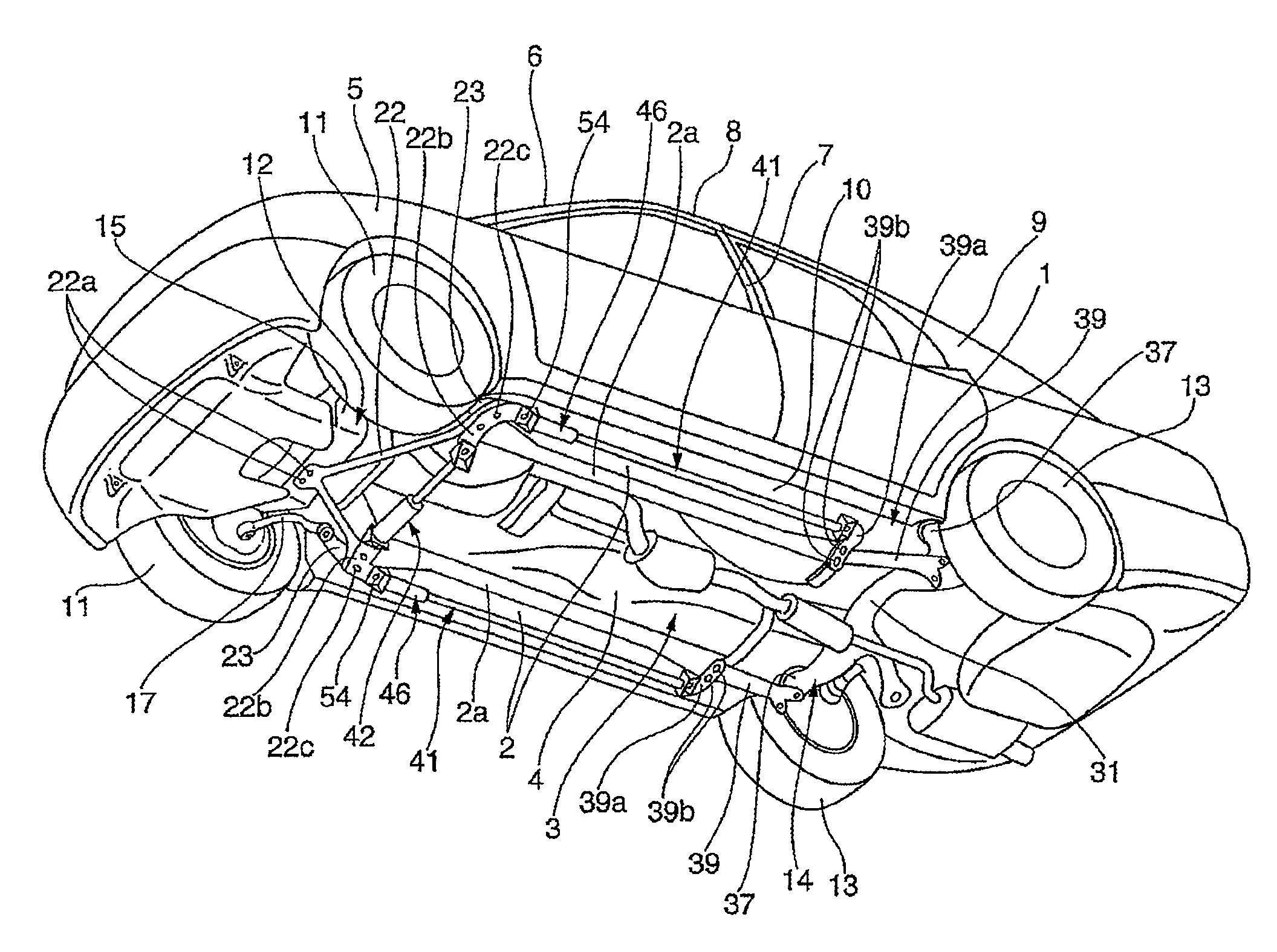
[0030]An embodiment of a vehicle body reinforcement device for vehicles is described below with reference to the FIGS. 1 to 6. The vehicle body reinforcement device may be used to reinforce the vehicle body of motor vehicles, such as passenger cars, trucks, and buses, for example but without limitation.

[0031]In these figures, the reference numeral 1 denotes a monocoque body as a vehicle body frame for an automobile according to this embodiment. This monocoque body 1, as shown in FIG. 1, includes: right and left side frames 2, 2 that extend in a longitudinal direction on both sides of the vehicle body; a floor panel 4 that defines an underbody 3 together with the side frames 2, 2; front fender aprons 5; front pillars 6; center pillars 7; a roof 8; rear pillars 9; and side sills 10. This monocoque body 1 is fabricated by combining and welding together a plurality of press-formed plate members and pipes. The side frame 2 comprises an integrally formed ridge 2a of a square-cornered U-sh...


PUM


Abstract

A vehicle body reinforcement device comprises an elongated shape with its middle portion comprising a hydraulic damper that produces a damping force against longitudinal deformation. Two vehicle body reinforcement devices may be mounted in a longitudinal manner to a vehicle body frame with a lateral space being defined between the two devices. Both ends of each of the vehicle body reinforcement devices can be removably attached from outside of the vehicle to positions that are exposed outside of the passenger compartment and below the vehicle body.

Description

CROSS-REFERENCE TO RELATED APPLICATIONS[0001]This application is a National Phase application of International Application No. PCT / JP2006 / 302154, filed Feb. 8, 2006, which claimed priority to Japanese Application No. 2005-048517, filed Feb. 24, 2005, each of which is hereby incorporated by reference in its entirety.BACKGROUND OF THE INVENTION[0002]1. Field of the Invention[0003]This invention generally relates to a vehicle body reinforcement devices for vehicles. More particularly, the present invention relates to such devices that can improve ride comfort while reducing vibrations generated by reinforcement.[0004]2. Description of the Related Art[0005]Conventionally, there has been a practice of using retrofit reinforcement members, such as the members disclosed in U.S. Pat. No. 5,411,311 (hereinafter simply referred to as Patent Document 1) to increase the strength of the vehicle body frame based upon driving conditions and driver's preference. The reinforcement member disclosed i...

Claims


Application Information

Patent Timeline
Patent Type & Authority Patents(United States)
IPC IPC(8): B62D21/00
CPCB62D21/15B62D25/00B62D25/20F16F9/54B60G2206/014B60G2206/605
Inventor HARADA, TOYOJISAKAI, KOUJI
Owner YAMAHA MOTOR CO LTD
Why Eureka
Try Eureka