Ink jet head driving method and apparatus

a driving method and jet head technology, applied in the direction of printing, other printing apparatus, etc., can solve the problems of difficult control of the size of ink droplets, increased power consumption, and degraded print quality, and achieve the effect of improving unstable ejection or degraded print quality and high speed printing

Active Publication Date: 2010-02-16
TOSHIBA TEC KK
View PDF19 Cites 2 Cited by
  • Summary
  • Abstract
  • Description
  • Claims
  • Application Information

AI Technical Summary

Benefits of technology

[0014]It is an object of the present invention to provide an ink jet head driving method and driving apparatus which is capable of improving unstable ejection or degraded print quality while the uniformed ejection speed and ejection quantity of each drop are achieved by increasing the ejection speed of ink drops from a first drop to subsequent several drops in multi-drop driving, and which is capable of achieving high speed printing by applying a boost pulse only in the case where the number of ink droplets is small and by disabling applying of the boost pulse in the case where the number of ink droplets is large.

Problems solved by technology

In this case, although resolution is not sacrificed, there is a problem that a technique for controlling the size of an ink droplet is difficult.
Thus, there is a problem that ejection becomes unstable or print quality is degraded because of a small amount of ejection.
However, there is a problem that power consumption is increased, and a heating rate is increased by increasing a voltage.
In addition, there is a problem that ejection becomes unstable because the ejection speed of the second and subsequent droplets becomes too high or print quality is degraded due to displacement in ink deposition between gradations, resulting from the increased difference in ejection speed of each droplet.
This boost pulse is redundantly applied, whereby a time of an entire drive cycle is extended, and therefore, such an extended time is disadvantageous for high speed printing.

Method used


Image

  • Ink jet head driving method and apparatus
  • Ink jet head driving method and apparatus
  • Ink jet head driving method and apparatus

Examples


Embodiment Construction

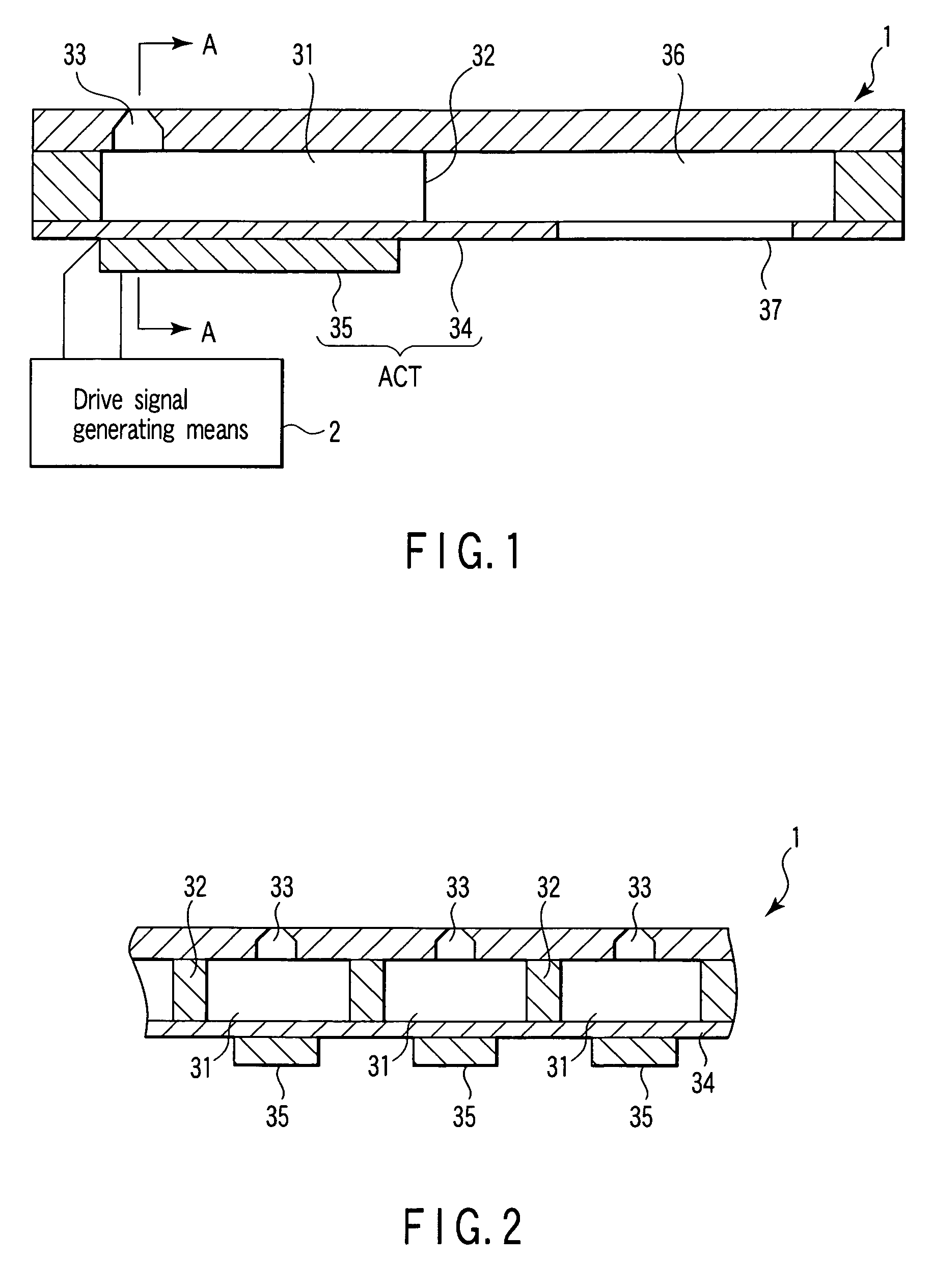
[0033]Hereinafter, an embodiment of the present invention will be described with reference to the accompanying drawings. FIGS. 1 and 2 are views each showing a construction of essential portions in an ink jet printing apparatus. FIG. 2 is a sectional view taken along the line A-A of FIG. 1.

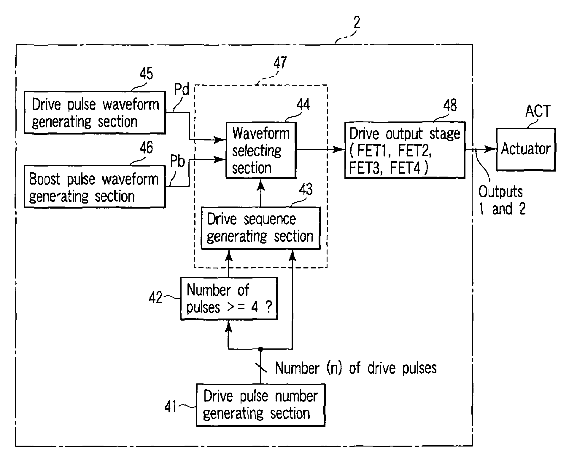
[0034]In FIGS. 1 and 2, reference numeral 1 denotes an ink jet head; and reference numeral 2 denotes drive signal generating means. The ink jet head 1 is formed while a plurality of pressure chambers 31 housing ink is partitioned by a bulkhead 32, and nozzles 33 for ejecting ink droplets are provided in the pressure chamber 31, respectively. A bottom face of each of the pressure chambers 31 is formed of a vibration plate 34, and a plurality of piezoelectric members 35 is fixed in correspondence with each of the pressure chambers at the lower face side of the vibration plate 34. The vibration plate 34 and the piezoelectric member 35 constitute an actuator ACT, and the piezoelectric member is electr...


PUM


Abstract

In an ink jet head driving method for applying a drive pulse to an actuator ACT to change capacities of a plurality of pressure chambers in which ink has been filled, ejecting an ink droplet from a nozzle formed in communication with the pressure chamber to print onto a printing medium, and moreover, controlling the number of ink droplets ejected according to the number of drive pulses to carry out gradation printing, a control is made such that, in the case where the number of ink droplets is small, a boost pulse Pb for amplifying a pressure vibration of the pressure chamber is applied prior to a drive pulse for ejecting a first ink droplet, and in the case where the number of ink droplets is large, applying of the boost pulse Pb is disabled.

Description

CROSS-REFERENCE TO RELATED APPLICATIONS[0001]This is a Continuation-in-Part application of U.S. patent application Ser. No. 11 / 311,683, filed Dec. 19, 2005, now U.S. Pat. No. 7,452,042, the entire contents of which are incorporated herein by reference.[0002]This application is based upon and claims the benefit of priority from prior Japanese Patent Applications No. 2005-176463, filed Jun. 16, 2005; and No. 2006-163337, filed Jun. 13, 2006, the entire contents of both of which are incorporated herein by reference.BACKGROUND OF THE INVENTION[0003]1. Field of the Invention[0004]The present invention relates to an ink jet head driving method and driving apparatus for changing the capacity of a pressure chamber in which ink has been filled by a piezoelectric element in response to a print signal, and then, ejecting an ink droplet from a nozzle which communicates with the pressure chamber by the resulting pressure change, thereby printing a character or an image and the like on a printing...

Claims


Application Information

Patent Timeline
Patent Type & Authority Patents(United States)
IPC IPC(8): B41J29/38
CPCB41J2/04581B41J2/04588B41J2/04596B41J2/04598B41J2/04595
Inventor NORIGOE, TAKASHI
Owner TOSHIBA TEC KK
Why Eureka
Try Eureka