Eureka AIR delivers breakthrough ideas for toughest innovation challenges, trusted by R&D personnel around the world.

Dispensing unit

a technology of dispensing unit and dispensing chamber, which is applied in the direction of liquid transfer device, single-unit apparatus, instruments, etc., can solve the problems of undesirable temporary closure and reopening of reservoirs, the withdrawal of known dispensing units, and the field of filling dispensing units

Active Publication Date: 2010-02-02
AIRSPRAY INT
View PDF22 Cites 119 Cited by
  • Summary
  • Abstract
  • Description
  • Claims
  • Application Information

AI Technical Summary

Benefits of technology

[0005]The object of the invention is to provide a combination of containers for assembling a dispensing unit, in which the containers do not have to be coupled immediately after they have been filled (although the invention does permit this option).
[0008]For example, it is conceivable for the reservoirs to be filled, the pumps to be put in place and the filled containers then to be stored in the uncoupled state in order to be coupled in the desired combination at a later stage. It is also possible for the containers to be coupled immediately after they have been filled, in which case it is then possible to achieve a liquid-tight state immediately after the containers have been filled and the pump has been put in place, thus preventing spillage of liquid and / or introduction of impurities into the reservoir.
[0009]Furthermore, it is conceivable for the containers to be sold in the uncoupled state, so that the user can make up the desired combination. On the other hand, it is also possible for the coupling to be produced in the factory and to be more or less permanent, so that it cannot be detached, or can only be detached with difficulty, by the user.
[0015]In an alternative embodiment of the dispensing unit according to the invention, the dispensing unit comprises a reservoir holder which at least partially holds the first and second reservoirs. A reservoir holder of this type ensures a good, stable connection between the two containers.

Problems solved by technology

A drawback of the known dispensing unit resides in particular in the field of the production of filled dispensing units.
This temporary closure and reopening of a reservoir is undesirable.

Method used


Image

  • Dispensing unit
  • Dispensing unit
  • Dispensing unit

Examples


Embodiment Construction

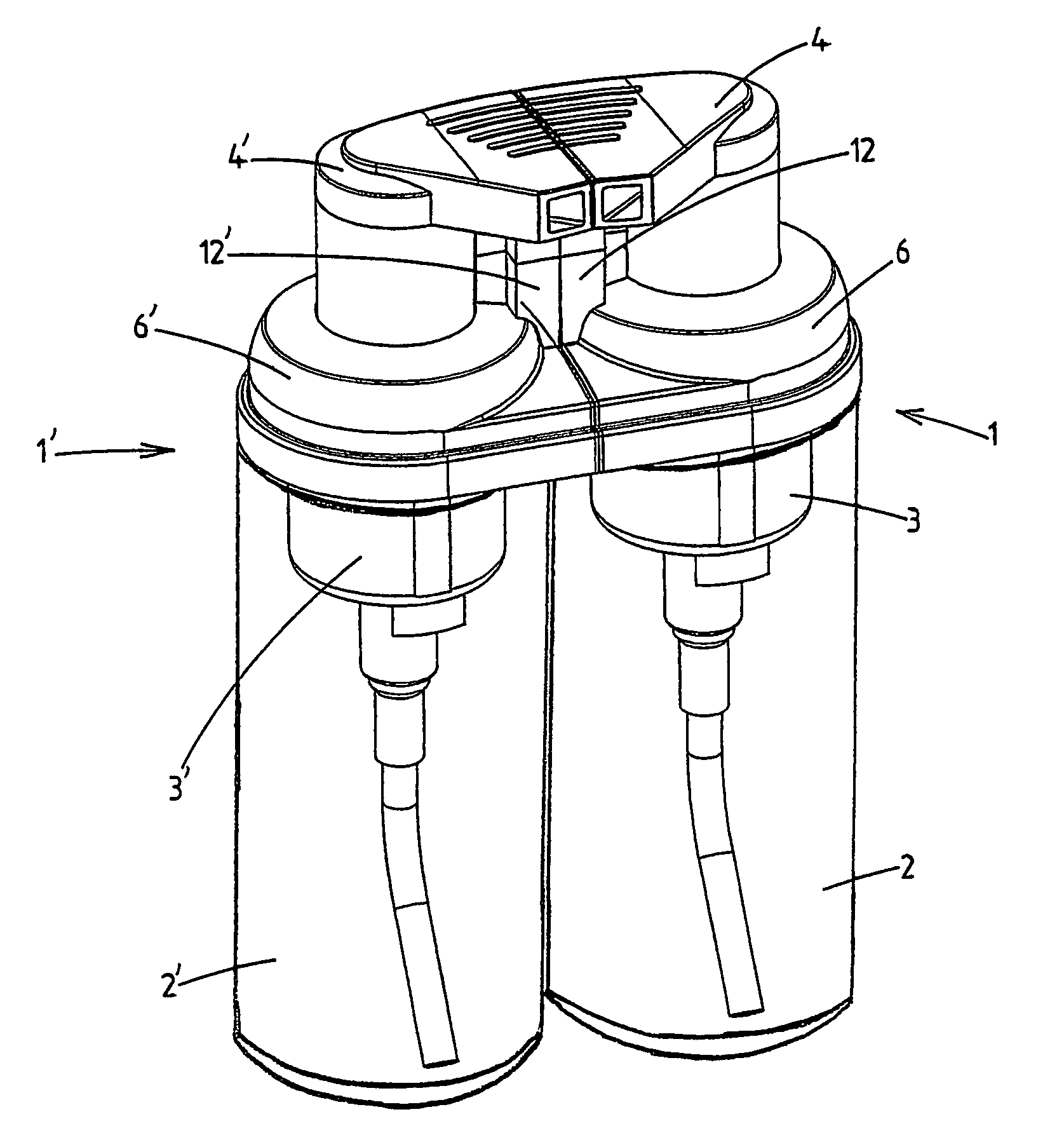
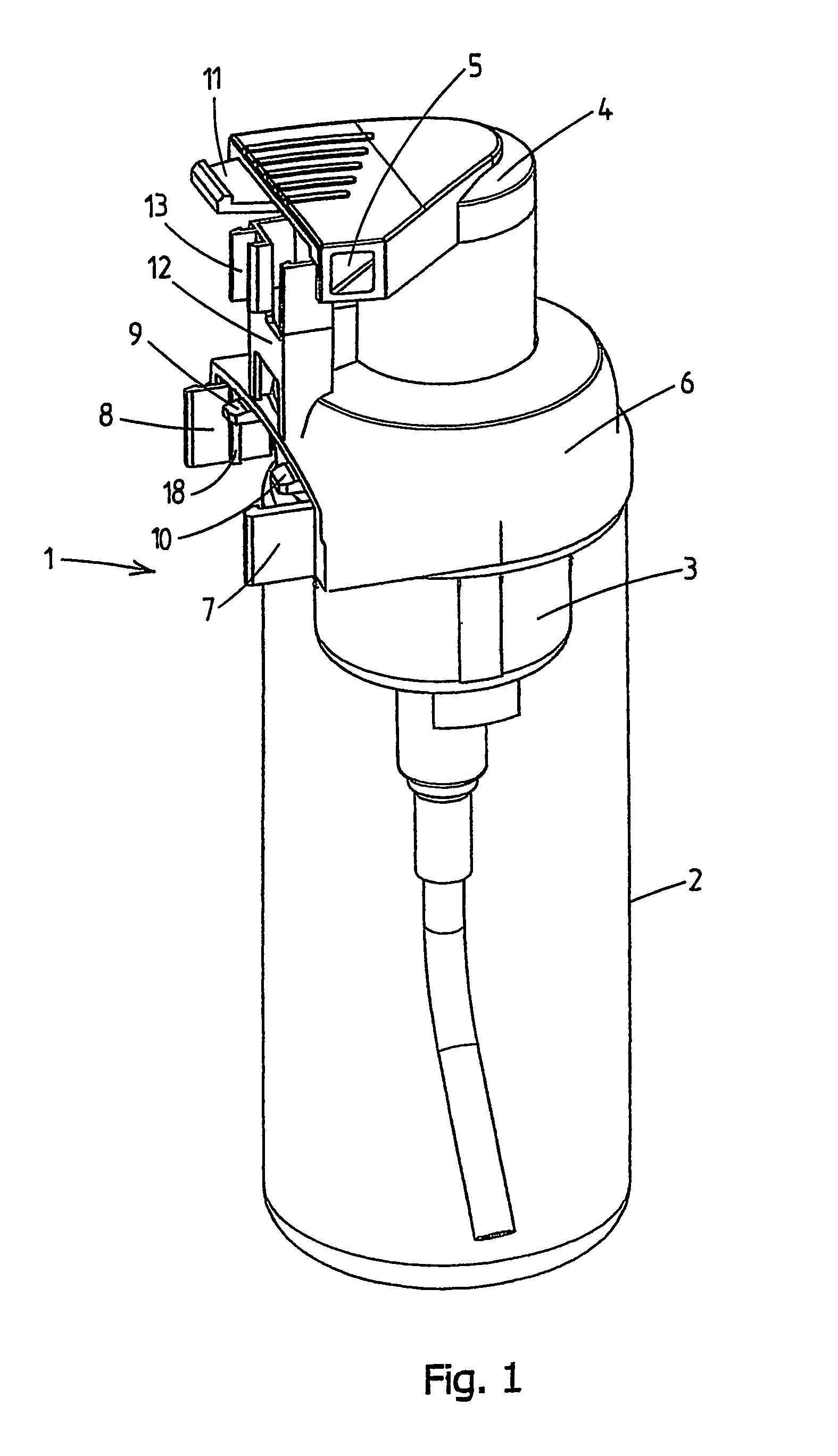
[0025]FIG. 1 shows an embodiment of a container according to the invention which is denoted overall by reference numeral 1. The container 1 comprises a reservoir 2 for a liquid substance, which can be pumped out of the reservoir 2 and dispensed by means of a pump 3 which can be actuated by hand, for example in the form of a foam.

[0026]The reservoir 2 has a base and an opening at the top side, into which the housing of the pump 3 fits.

[0027]The pump 3 can be actuated using a pump-actuating button 4, which can be moved up and down, on the top side of the pump 3, during which process a liquid, for example in foam form, flows through a dispensing passage to a dispensing opening 5 in the button 4, where it is dispensed. The dispensing passage in this case runs through the button 4.

[0028]In the case of foam, the foam can be obtained as a result of a liquid being mixed with air in the reservoir.

[0029]It is also possible for one of the reservoirs or both reservoirs to be of the airless type...


PUM


Abstract

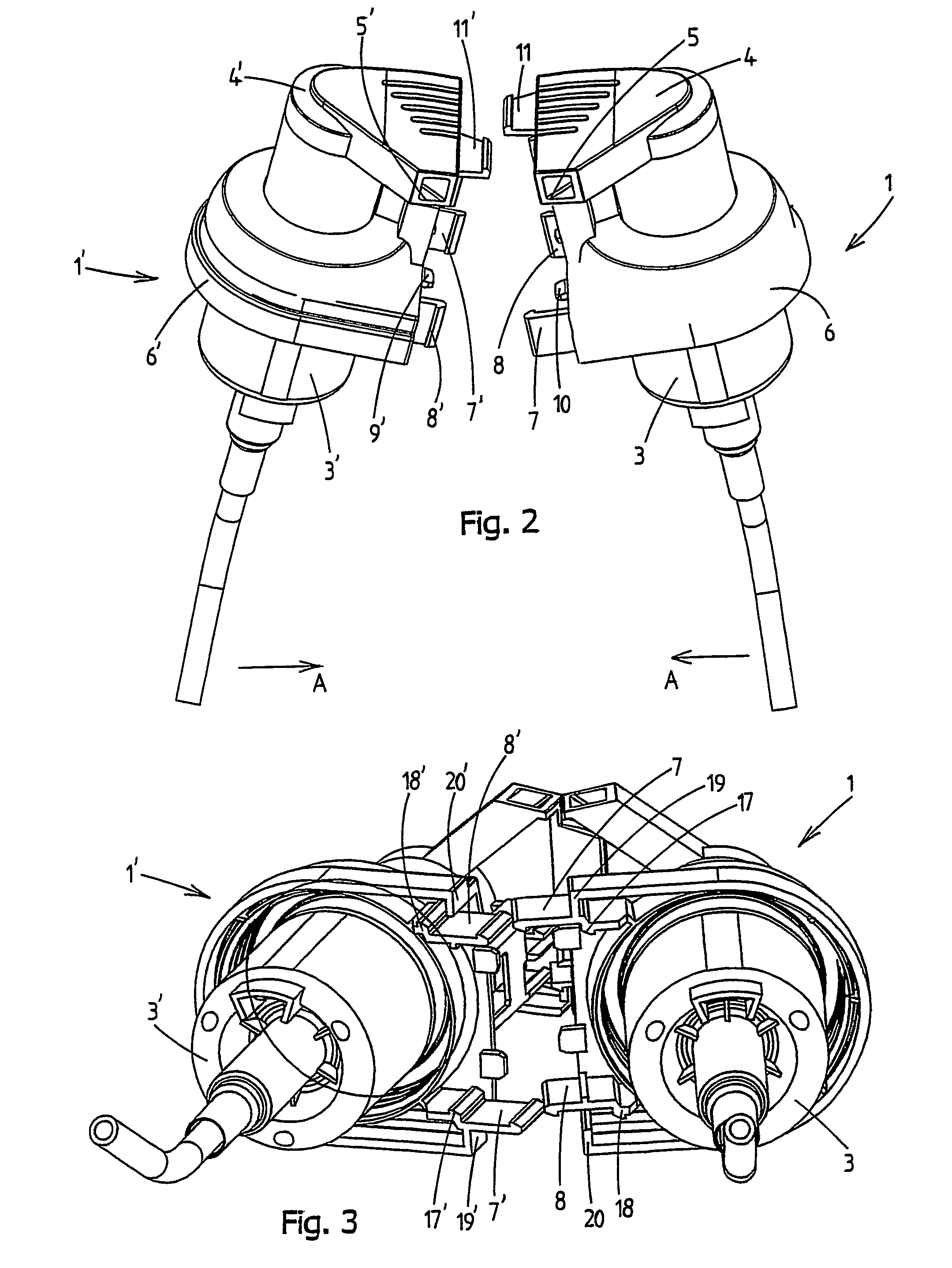
The invention relates to a combination of a first container and a second container to form a dispensing unit. The first and second containers each have a reservoir for a liquid substance and pump which is secured to the reservoir, can be actuated by hand and has a dispensing opening and a pump-actuating button for dispensing substance from the reservoir. The combination also comprises coupling means for coupling together the first and second containers in a position next to one another. The invention is characterized in that the coupling means comprise: one or more first coupling members, which are each arranged on the first container, and one or more second coupling means, which are each arranged on the second container and which can each be directly coupled to an associated first coupling member on the first container. It is preferable for a first coupling member and an associated second coupling member each to be arranged fixedly on the assembly of reservoir and pump of the associated container in order to create a stable coupling between the assemblies reservoir and pump of the two containers.

Description

[0001]This application is the National Stage of International Application No. PCT / NL03 / 00182, filed 11 Mar. 2003, which claims the benefit of Netherlands Application No. NL 1020200, filed 19 Mar. 2002, which claims the benefit of Netherlands Application No. NL 1022197, filed 18 Dec. 2002, the contents of which is incorporated by reference herein.FIELD OF THE INVENTION[0002]The present invention relates to a combination of a first container and a second container to form a dispensing unit for liquid substances in accordance with the preamble of claim 1.BACKGROUND OF THE INVENTION[0003]EP 0 243 667 has disclosed a dispensing unit with two containers which each have a reservoir for a liquid substance. On the top side, each of the containers has an opening in which a pump is positioned. The containers are connected to one another in a position next to one another by a common bridge piece. The bridge piece has two openings, in which the open end of the respective containers can be positi...

Claims


Application Information

Patent Timeline
IPC IPC(8): B67D7/70B65D83/76B05B11/00
CPCB05B11/3084B05B11/3059B05B11/1059B05B11/1084B05B11/00B65D47/00
Inventor VAN DER HEIJDEN, EDGAR IVO MARIA
Owner AIRSPRAY INT
Why Eureka
Eureka Blog
Learn More