
Surveillance camera

a technology of surveillance camera and camera body, which is applied in the field of surveillance cameras, can solve the problems of difficult mounting of >) damage to the camera body (b>80/b>), and difficulty in mounting on the ceiling or wall, so as to achieve clearer and more complete images, wide illumination field, and intense light

Inactive Publication Date: 2010-01-26
PAL TATE INDAL
View PDF9 Cites 31 Cited by
  • Summary
  • Abstract
  • Description
  • Claims
  • Application Information

AI Technical Summary

Benefits of technology

"The present invention provides a surveillance camera with adequate illumination to cover its field of view. The camera has a positioning base, mounting base, globe, and camera assembly. The mounting base can latch onto the positioning base and has a tapered sidewall, panel recess, and LEDs. The LEDs provide a wider field of illumination and more intense light. The camera assembly is attached pivotally to the mounting base, allowing for clearer and more complete images. The technical effects of this invention are improved surveillance camera performance and better image quality."

Problems solved by technology

Furthermore, the surveillance camera with the camera assembly (80) mounted in the base (60) is difficult to mount on a ceiling or wall and aim precisely at the area of interest.
Thus, several attempts are often required to mount and aim the surveillance camera precisely, during which the camera assembly (80) might be damaged.
The whole surveillance camera must often be removed from the ceiling or the wall to be maintained, which is troublesome and might cause the ceiling or the wall to become unsightly.

Method used


Image

  • Surveillance camera
  • Surveillance camera
  • Surveillance camera

Examples


Embodiment Construction

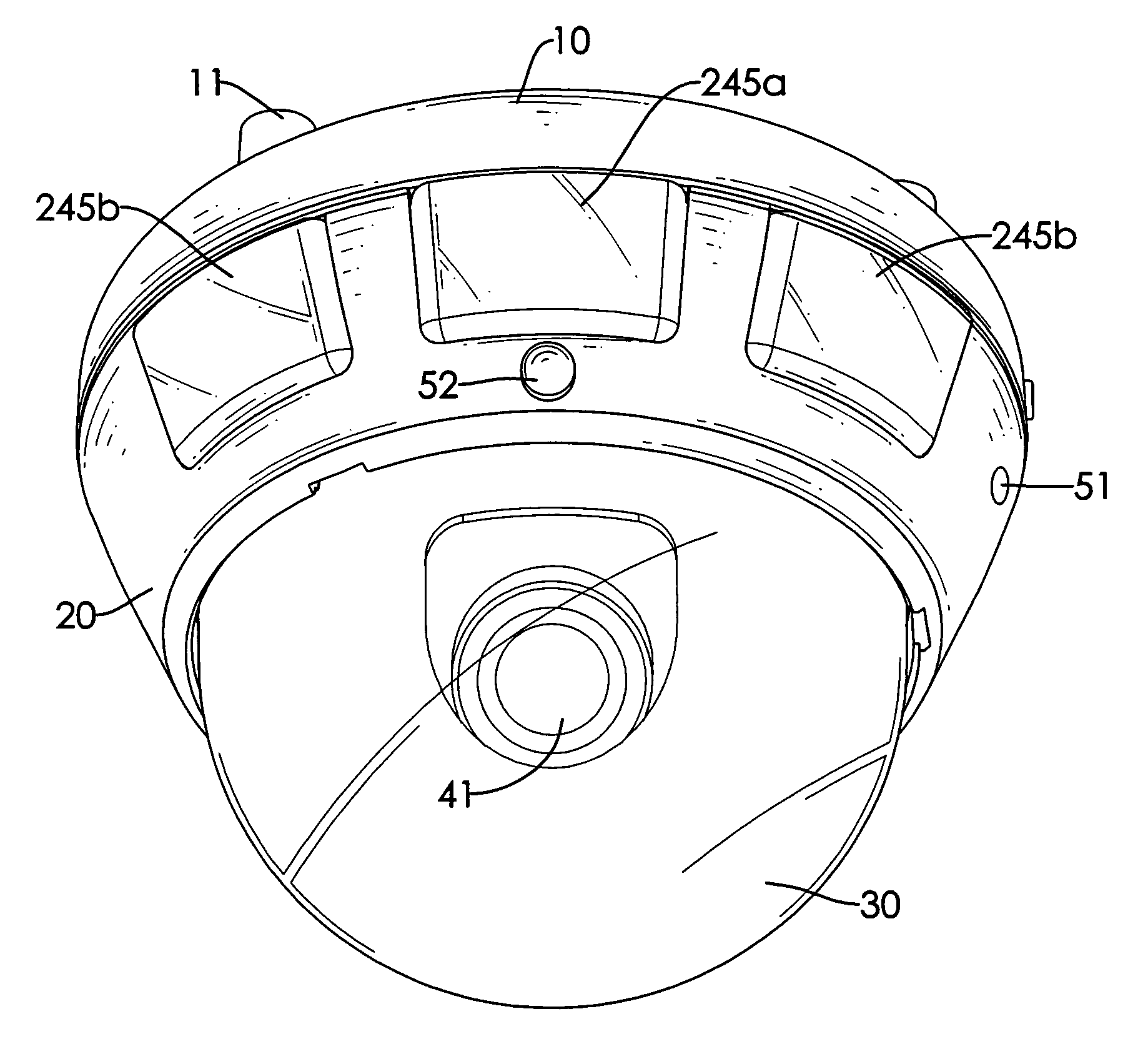
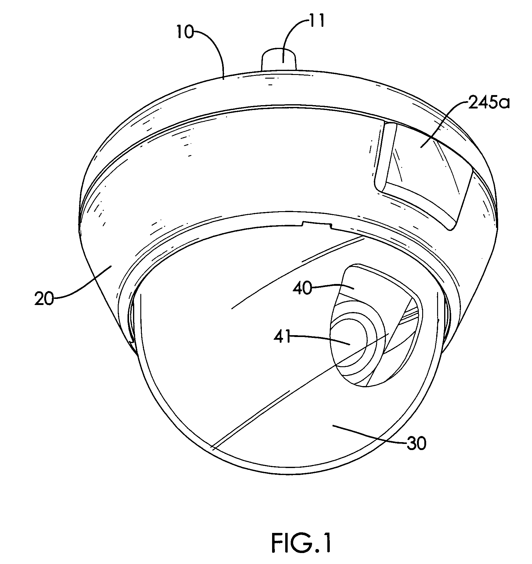
[0023]With reference to FIGS. 1 and 5, a surveillance camera in accordance with the present invention comprises an optional positioning base (10), a mounting base (20), a globe (30), a camera assembly (40), an optional light sensor (51) and an optional Passive Infrared (PIR) sensor (52).

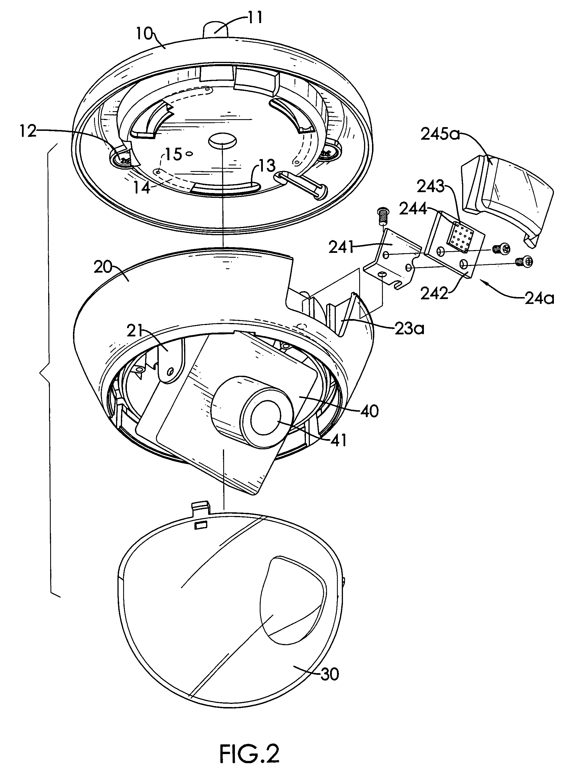
[0024]With further reference to FIG. 2, the positioning base (10) is attached to a ceiling, a wall or the like and has a fastening surface, an inner surface, multiple tubes (11), multiple optional screws (12), multiple through holes (13), multiple optional attachment slots (14) and multiple optional detents (15). The tubes (11) protrude from the fastening surface of the positioning base (10), and each tube (11) has a distal end. The screws (12) are mounted respectively through the tubes (11) and protrude from the distal ends of the tubes (11) to attach the positioning base (10) to a ceiling, a wall or the like. The through holes (13) are curved and are formed through the positioning base (10). The at...


PUM


Abstract

A surveillance camera has a positioning base, a mounting base, a globe and a camera assembly. The positioning base is attached to a ceiling or a wall or the like. The mounting base may latch to or detach from the positioning base and has a tapered sidewall, a panel recess formed in the sidewall and an illuminator mounted in the panel recess. The illuminator illuminates an area of interest and has multiple light-emitting diodes (LEDs) mounted on a substrate. The LEDs provide a wider field of illumination and more intense light. The camera assembly is attached pivotally to the mounting base. Therefore, the surveillance camera can get clearer and more complete images.

Description

BACKGROUND OF THE INVENTION[0001]1. Field of the Invention[0002]The present invention relates to a surveillance camera, especially to a camera that has a light-emitting diode module and a wide illuminating field.[0003]2. Description of the Prior Arts[0004]Surveillance cameras are attached to a ceiling, a wall or the like of buildings, especially in elevators, or at important intersections to record or monitor events in those places and provide instant reports or powerful evidence against criminal activity.[0005]With reference to FIG. 6, a conventional surveillance camera has a base (60), a globe (70), a bracket and a camera assembly (80).[0006]The base (60) is attached securely to a ceiling, a wall or the like to point the surveillance camera at a specific area of interest and has an inner surface and a recess. The recess is formed in the inner surface of the base (60).[0007]The globe (70) is mounted against the inner surface of the base (60) and covers the recess of the base (60).[...

Claims


Application Information

Patent Timeline
Patent Type & Authority Patents(United States)
IPC IPC(8): G03B17/00H04N5/225
CPCG03B15/03
Inventor WEN, PEI-CHUN
Owner PAL TATE INDAL
Learn More