
Medicine supply apparatus

a technology for supplying apparatus and medicine, which is applied in the direction of instruments, packaging goods, de-stacking articles, etc., can solve the problems of complicated electrical circuit of tablet cases, inability to discharge medicine, and increased costs, and achieves the effect of improving convenience and being convenient to indica

Active Publication Date: 2009-12-29
PHC HLDG CORP
View PDF22 Cites 50 Cited by
  • Summary
  • Abstract
  • Description
  • Claims
  • Application Information

AI Technical Summary

Benefits of technology

The present invention provides a medicine supply apparatus that simplifies the exchange of tablet cases and the structure of the apparatus itself. The apparatus includes a plurality of tablet cases for accommodating medicines and a case accommodating section of a main body. The apparatus also includes an identifier on each tablet case with identification information for identifying the tablet case. A reader is provided to read the identification information. The apparatus further includes a control device that controls the discharge of medicine from the tablet case. The apparatus can detect and address motor failures, improving operational performance and convenience. The identification means can be an optically readable identification code on the tablet case, simplifying the electric circuit and reducing costs.

Problems solved by technology

In accordance with such a conventional method, however, the electric circuit for the tablet case becomes complicated, and costs are increased.
If a motor for driving this discharge drum is disconnected, however, medicine cannot be discharged.
However, disconnection of motors cannot be determined visually.
Thus, there arises the problem in which it takes a long time to specify causes of failure and perform maintenance for corresponding parts.
The aforementioned motor, solenoid, thermal sealing device and printer are parts that wear out and thus have their own durability limits.
If such parts are broken, supply of medicine may be stopped.
This requires work by human hand, and further, errors may occur, resulting in confusion.

Method used


Image

  • Medicine supply apparatus
  • Medicine supply apparatus
  • Medicine supply apparatus

Examples


Embodiment Construction

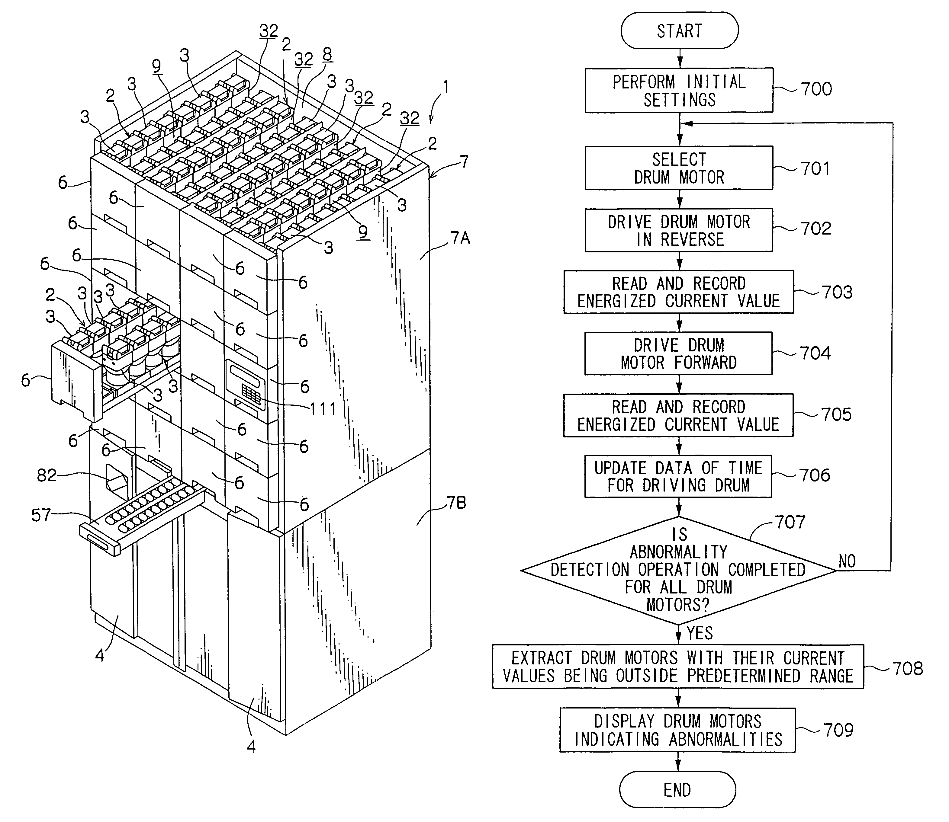
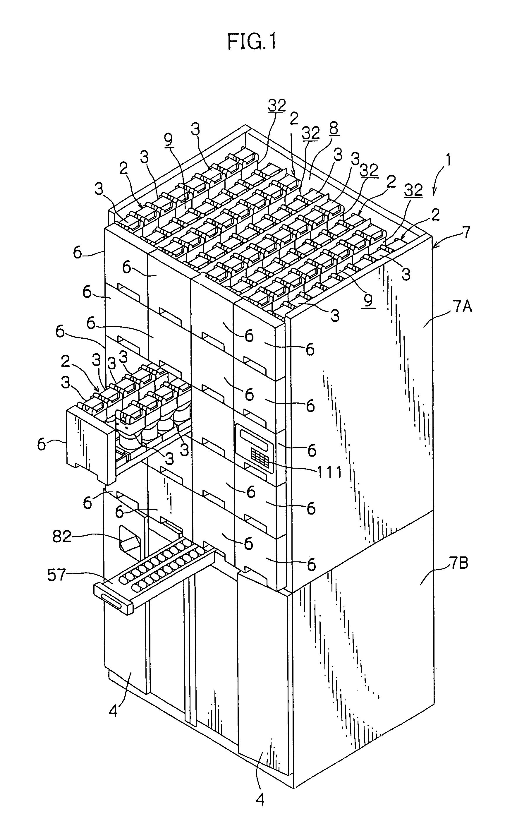
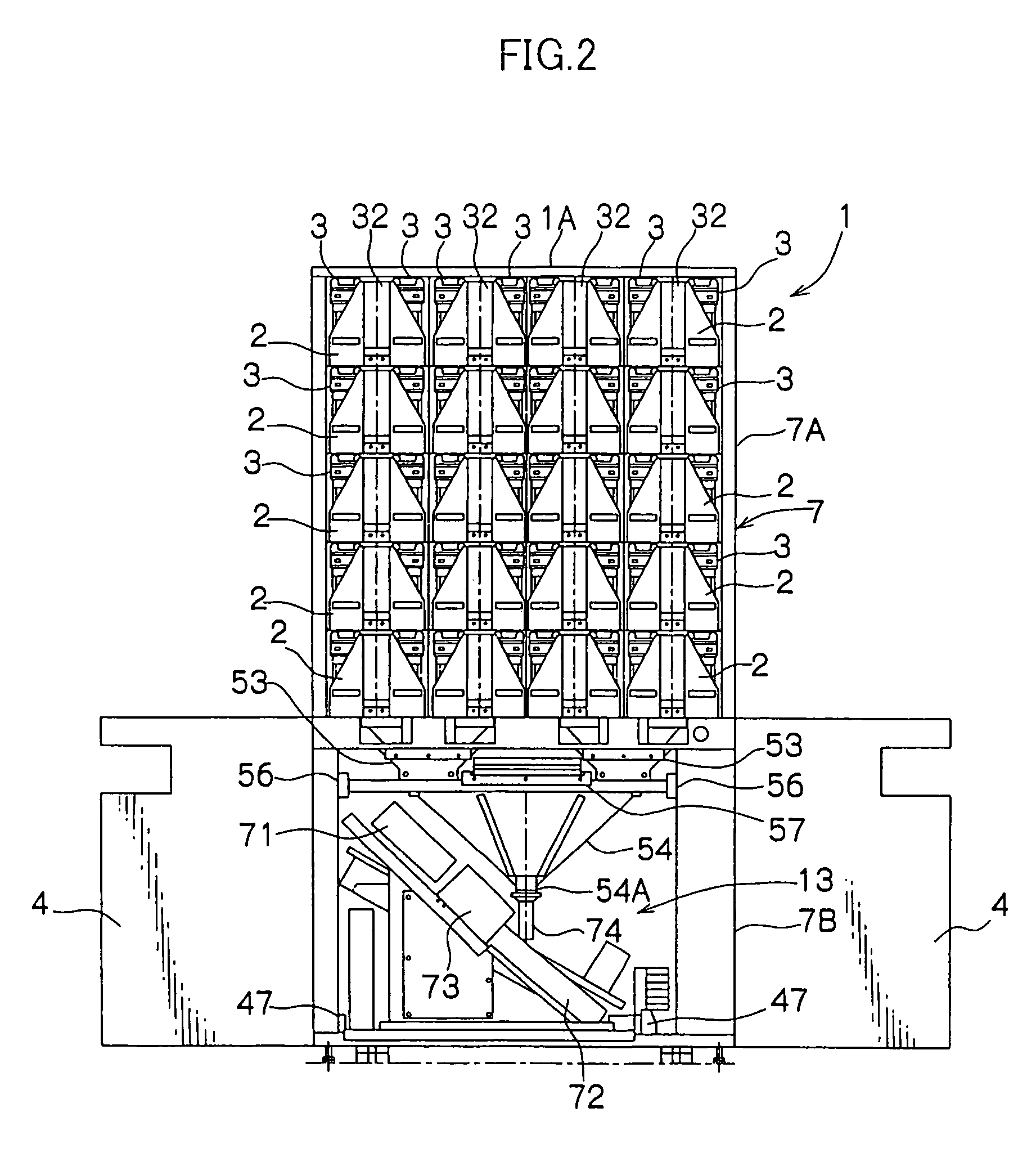
[0101]Embodiments of the present invention will be described hereinafter in detail with reference to the drawings. FIG. 1 is a perspective view of a medicine supply apparatus 1 according to an embodiment of the invention (with a top roof 1A being removed). FIG. 2 is a front view of the medicine supply apparatus 1 with door panels 6 of shelves 2 being removed and lower panels 4 being opened. FIG. 3 is a vertical sectional view of the medicine supply apparatus 1. FIG. 4 is another front view of the medicine supply apparatus 1. FIG. 5 is a side view of the medicine supply apparatus 1. FIG. 6 is a flat view of the medicine supply apparatus 1. FIG. 7 is a perspective view of the shelf 2. FIG. 8 is a perspective view of the shelf 2 with accommodating containers 51 of tablet cases 3 being removed. FIG. 9 is a perspective view of the accommodating container 51 of the tablet case 3. FIG. 10 is an exploded perspective view of a driving base 52 of the tablet case 3. FIG. 11 is a perspective vi...


PUM

PropertyMeasurementUnit
timeaaaaaaaaaa
currentaaaaaaaaaa
timeaaaaaaaaaa

Abstract

A medicine supply apparatus which comprises, in a case accommodating section 8, a plurality of tablet cases 3 for accommodating medicine and charges or supplies medicine into a bag 72, which medicine has been discharged from each tablet case 3 based on a prescription. An identification code 26 is provided for each of the tablet cases 3 and read by an optical sensor 33 provided inside the case accommodating section 8, whereby discharge of medicine is controlled. A motor 14 for driving a discharge drum for the tablet case 3 is checked for disconnection by being regularly energized. The operating time and the frequency of operation of parts that wear out, such as the motors, are stored for use in failure prediction. Time slots in which medicine should be taken are printed, each in a different color, by a color printing mechanism 73 on the bag 72 into which medicine is charged.

Description

BACKGROUND OF THE INVENTION[0001]1. Field of the Invention[0002]The present invention relates to a medicine supply apparatus that is placed at hospitals and pharmacies and supplies the designated number of medicines accommodated within tablet cases into a container (a bottle or a bag) in accordance with a prescription.[0003]2. Description of the Related Art[0004]In hospitals and pharmacies, a medicine supply apparatus such as one disclosed in, for example, Japanese Utility Model Application Publication (JP-Y) No. 57-5282 (B65B1 / 30) has been conventionally used to provide medicines prescribed by doctors to patients. In accordance with such a system, the designated number of medicines (tablets, capsules and the like) described in a prescription are discharged one by one from discharge drums (referred to as aligning boards in JP-Y No. 57-5282) within tablet cases. The discharged medicines are collected in a hopper through a chute and then packaged in packaging paper or bottled in a bot...

Claims


Application Information

Patent Timeline
Patent Type & Authority Patents(United States)
IPC IPC(8): B65B57/00B65B5/10A61J3/00A61J7/00B65B61/26G07F11/62
CPCB65B5/103B65B61/26G07F9/026G07F17/0092G07F11/62G07F11/64G07F11/42B65B1/30B65B57/00A61J3/00
Inventor ISHIWATARI, HITOSHIUEMA, SHINYAHARAGUCHI, MANABUKOBAYASHI, KOICHINAKAMURA, SHIGEYUKI
Owner PHC HLDG CORP
Learn More