
Optical device for superposing electronic images in front of an objective

an optical device and electronic image technology, applied in the field of optical devices, can solve problems such as optical combiners, and achieve the effect of good transmission of external scenery

Active Publication Date: 2009-12-22
THALES SA
View PDF6 Cites 2 Cited by
  • Summary
  • Abstract
  • Description
  • Claims
  • Application Information

AI Technical Summary

Benefits of technology

[0016]An object of the invention is to propose an alternative and compact optical solution, the combiner of which ensures very good transmission of the external scenery. This solution has an important advantage in relation to solutions of the prior art. It becomes possible for the pupil image of the optical device to coincide with the aperture of the objective. In this way, any vignetting of the field is avoided and a symbology is provided in a visual field as large as that of the objective.

Problems solved by technology

One of the difficulties of producing this type of device is producing the optical combiner.

Method used


Image

  • Optical device for superposing electronic images in front of an objective
  • Optical device for superposing electronic images in front of an objective
  • Optical device for superposing electronic images in front of an objective

Examples


Embodiment Construction

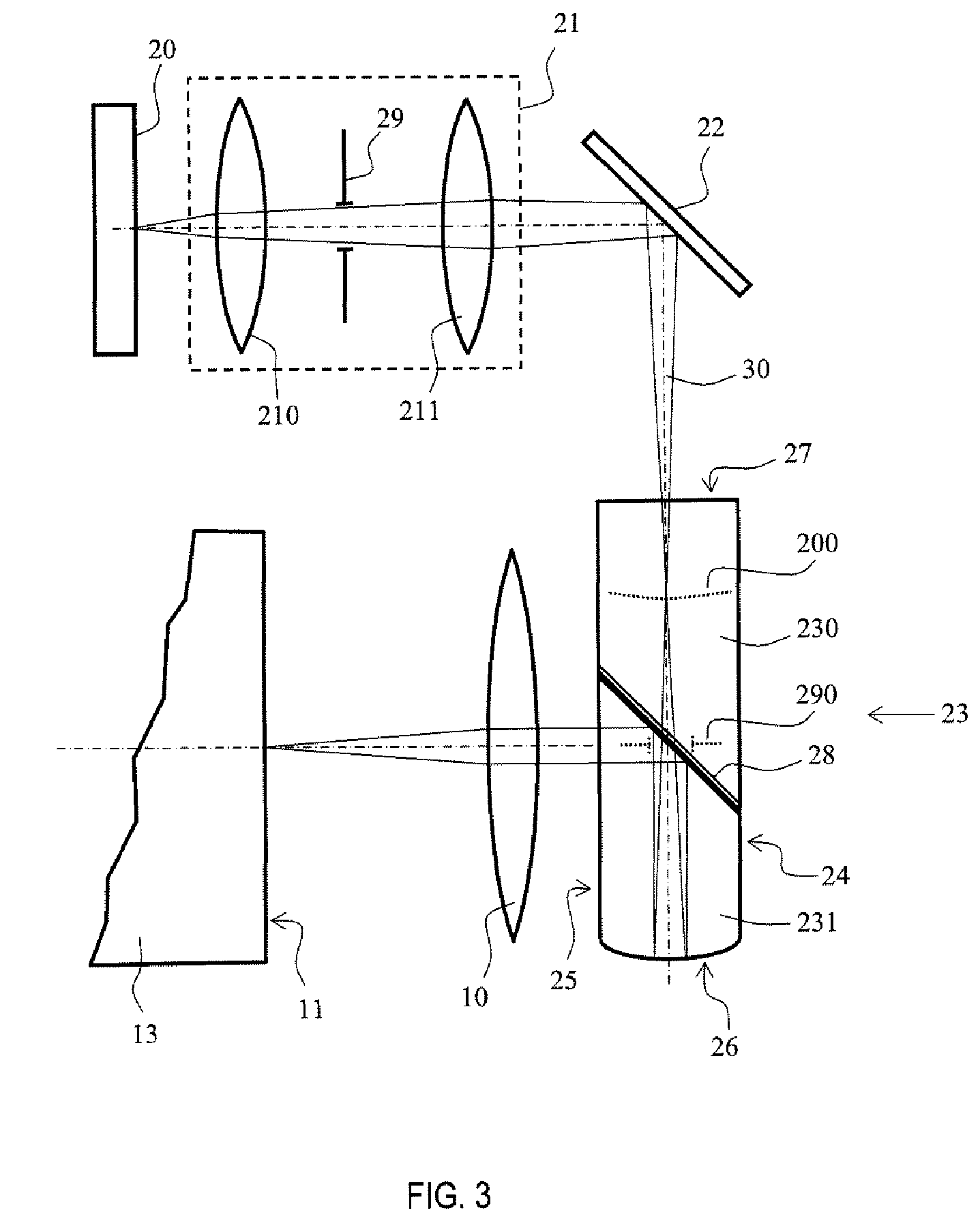
[0035]FIGS. 3, 4 and 5 show the principle of the optical device for superposing images according to the invention. It essentially comprises:[0036]an image source 20;[0037]an optical relay 21; and[0038]an optical combiner 23.

[0039]The optical device is placed in front of an optical module comprising at least:[0040]an objective 10; and[0041]a photosensitive or photoemissive surface 11 placed in the focal plane of said objective, said surface belonging, for example, to an amplifier device 13.

[0042]The image source may conventionally be a cathode ray tube or else a flat screen which may be:[0043]a liquid crystal display, known by the acronym LCD; or[0044]organic light-emitting diodes, known by the acronym OLED.

[0045]It is important that the optical characteristic of the image source be suited to the characteristics of the photoemissive surface. Thus, in the case where the photosensitive surface is that of a light-intensifying device, it is important that the following three points are t...


PUM


Abstract

The field of the invention is that of optical devices allowing the superposition of an electronic image on an image coming from an external scenery. The subject of the invention is an optical device for superposing images, designed to be positioned in front of an optical module comprising at least an objective and a photosensitive surface positioned in the focal plane of said objective. The device comprises an image source, an optical relay and an optical combiner formed of two optical parts assembled via an approximately plane common face including a weakly reflective coating. The combiner has the general form of a plate with plane parallel faces, the common face being inclined at around 45 degrees to said plane faces. It has an entrance face and a opposing face that are approximately perpendicular to the plane faces, the opposing face having approximately the form of a reflecting spherical surface. This device applies in particular to night vision goggles where, when the optical combiner is placed in front of the objective of a goggles body, it allows superposition of an electronic image on the external scenery while introducing marginal attenuation.

Description

CROSS-REFERENCE TO RELATED APPLICATIONS[0001]The present Application is based on International Application No. PCT / EP2006 / 066827, filed on Sep. 28, 2006, which in turn corresponds to French Application No. 0509951 filed on Sep. 25, 2005, and priority is hereby claimed under 35 USC §119 based on these applications. Each of these applications are hereby incorporated by reference in their entirety into the present application.BACKGROUND OF THE INVENTION[0002]1. Field of the Invention[0003]The field of the invention is that of optical devices allowing the superposition of an electronic image on an image coming from an external scenery.[0004]2. Description of the Prior Art[0005]For a certain number of applications it is useful to blend an electronic image into an image of an external scenery. Head-up displays used principally in the aeronautic field and more recently in the automobile field will be cited. In this case, an electronic image providing flight control or navigation informatio...

Claims


Application Information

Patent Timeline
Patent Type & Authority Patents(United States)
IPC IPC(8): G02B27/14
CPCG02B23/12G02B27/0081G02B27/0101G02B27/144G02B27/145G02B27/0172G02B2027/0138G02B2027/0118
Inventor FRANCOIS, JEAN-MICHELBOURGAIN, JEAN-LOUIS
Owner THALES SA
Learn More