
Fusion of multiple imaging planes for isotropic imaging in MRI and quantitative image analysis using isotropic or near-isotropic imaging

a technology of isotropic imaging and imaging plane, applied in the field of medical imaging, can solve the problems of not quantitatively available subjective visual inspection techniques, limit of 3d image analysis and visualization, etc., and achieve the effect of increasing resolution and improving image resolution

Active Publication Date: 2009-12-15
CONFORMIS
View PDF17 Cites 260 Cited by
  • Summary
  • Abstract
  • Description
  • Claims
  • Application Information

AI Technical Summary

Benefits of technology

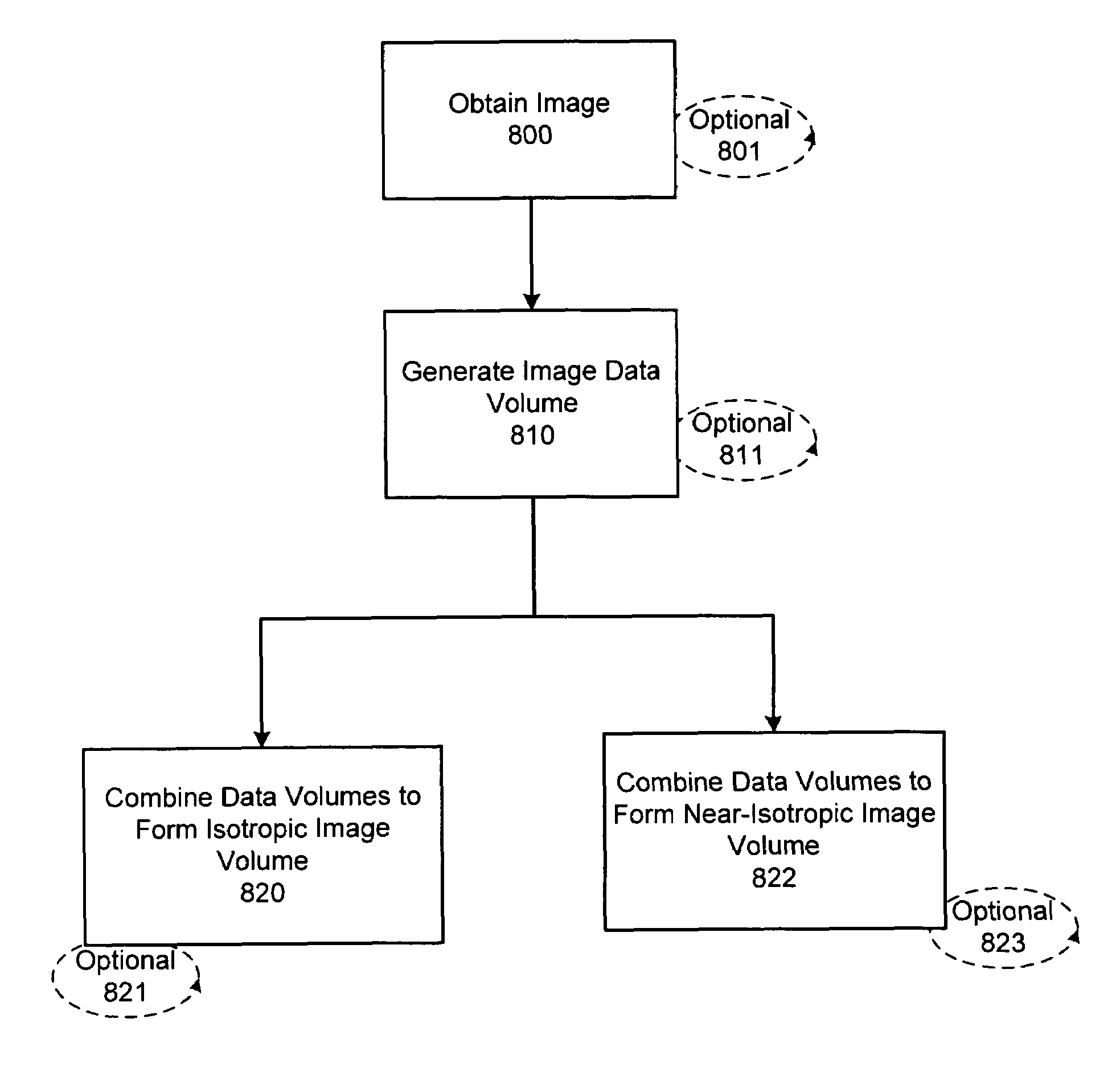
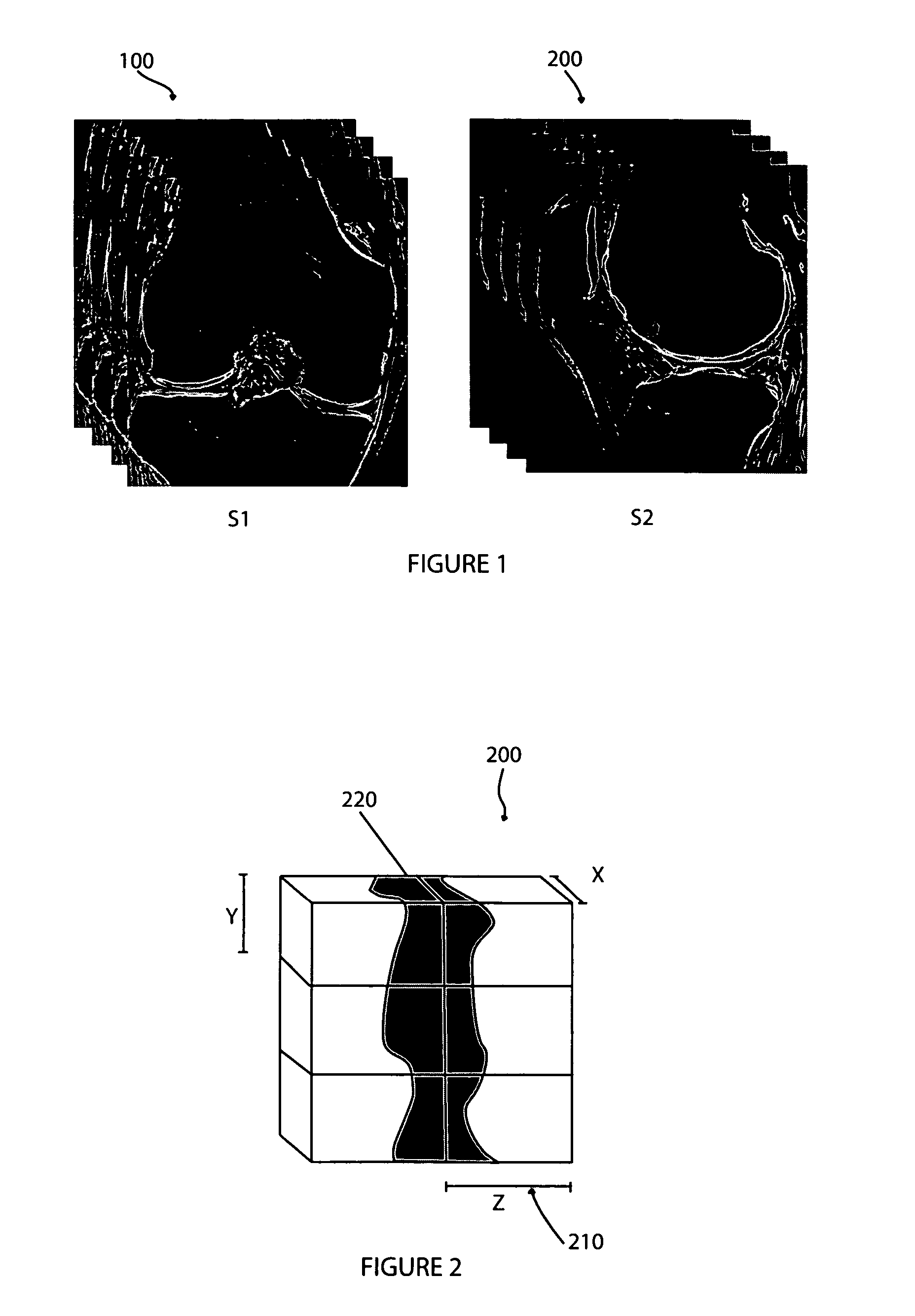
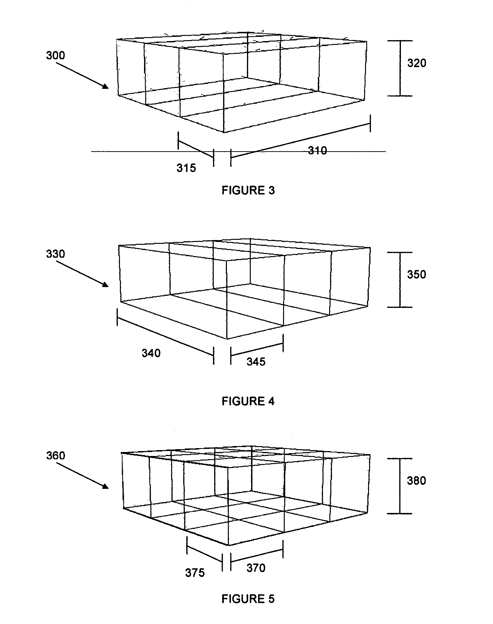
[0013]Thus, in one aspect, a method of improving resolution of images, such as MR images, is provided. In certain embodiments, the method includes, for example, obtaining at least two MR scans (e.g., scans in perpendicular planes) of a body part and merging the scans, thereby increasing resolution. In any of the methods described herein, the scans may be in any plane, for example, sagittal, coronal and / or axial imaging planes. Preferably, the second or subsequent scans contain a sufficient number of slices to cover the entire field of view of the first scan. Furthermore, in any of the methods described herein, the data obtained from the two or more scans are subsequently merged to form a new data volume, which is isotropic (or near-isotropic) and has a resolution corresponding to the in-plane resolution of S1 and S2. Merging may include, for example, determining a gray value for each voxel (V) of the new (merged) data volume. In certain embodiments, the gray values are obtained by: (a) determining the position in 3D space for V; (b) obtaining (e.g., from the original scans) gray values of the scans prior to fusion at this position; (c) interpolating (combining) gray values from S1 and S2 into a single gray value (G); and (d) assigning G to V.

Problems solved by technology

The low resolution between the slices (typically in z-direction) leads to limitations with respect to 3D image analysis and visualization.
Currently available subjective visual inspection techniques are not quantitative and, additionally, are often inaccurate.

Method used


Image

  • Fusion of multiple imaging planes for isotropic imaging in MRI and quantitative image analysis using isotropic or near-isotropic imaging
  • Fusion of multiple imaging planes for isotropic imaging in MRI and quantitative image analysis using isotropic or near-isotropic imaging
  • Fusion of multiple imaging planes for isotropic imaging in MRI and quantitative image analysis using isotropic or near-isotropic imaging

Examples


Embodiment Construction

[0033]The following description is presented to enable any person skilled in the art to make and use the invention. Various modifications to the embodiments described will be readily apparent to those skilled in the art, and the generic principles defined herein can be applied to other embodiments and applications without departing from the spirit and scope of the present invention as defined by the appended claims. Thus, the present invention is not intended to be limited to the embodiments shown, but is to be accorded the widest scope consistent with the principles and features disclosed herein. To the extent necessary to achieve a complete understanding of the invention disclosed, the specification and drawings of all issued patents, patent publications, and patent applications cited in this application are incorporated herein by reference.

[0034]As will be appreciated by those of skill in the art, methods recited herein may be carried out in any order of the recited events which ...


PUM

PropertyMeasurementUnit
angleaaaaaaaaaa
angleaaaaaaaaaa
angleaaaaaaaaaa

Abstract

In accordance with the present invention there is provided methods for generating an isotropic or near-isotropic three-dimensional images from two-dimensional images. In accordance with the present invention the method includes, obtaining a first image of a body part in a first plane, wherein the first image generates a first image data volume; obtaining a second image of the body part in a second plane, wherein the second image generates a second image data volume; and combining the first and second image data volumes to form a resultant image data volume, wherein the resultant image data volume is isotropic or near-isotropic.

Description

PRIORITY CLAIM[0001]This application claims the benefit of U.S. Provisional Patent Application Ser. No. 60 / 431,176, filed Dec. 4, 2002, the entirety of which is herein incorporated by reference.STATEMENT AS TO RIGHTS TO INVENTIONS MADE UNDER FEDERALLY SPONSORED RESEARCH AND DEVELOPMENT[0002]Certain aspects of the invention described below were made with United States Government support under Advanced Technology Program 70NANBOH3016 awarded by the National Institute of Standards and Technology (NIST). The United States Government may have rights in certain of these inventions.TECHNICAL FIELD[0003]This invention relates generally to medical imaging, and more specifically to medical imaging that facilitates analysis in more than one dimension, e.g. magnetic resonance imaging (MRI). More particularly the invention relates to isotropic imaging techniques used in medical imaging, such as MRI, to improve quantitative image analysis.BACKGROUND OF THE INVENTION[0004]Magnetic resonance imagin...

Claims


Application Information

Patent Timeline
Patent Type & Authority Patents(United States)
IPC IPC(8): G06K9/00A61B5/05G01R33/56
CPCG01R33/56B23P19/00Y10T29/49G01R33/5608A61B5/055
Inventor TSOUGARAKIS, KONSTANTINOSSTEINES, DANIELTIMSARI, BIJAN
Owner CONFORMIS
Learn More