Belt conveyance apparatus and image forming apparatus using such a belt conveyance apparatus
a technology of conveyance apparatus and belt, which is applied in the field of image forming apparatus to achieve the effect of correcting the deflection of the conveyance bel
- Summary
- Abstract
- Description
- Claims
- Application Information
AI Technical Summary
Benefits of technology
Problems solved by technology
Method used
Image
Examples
first embodiment
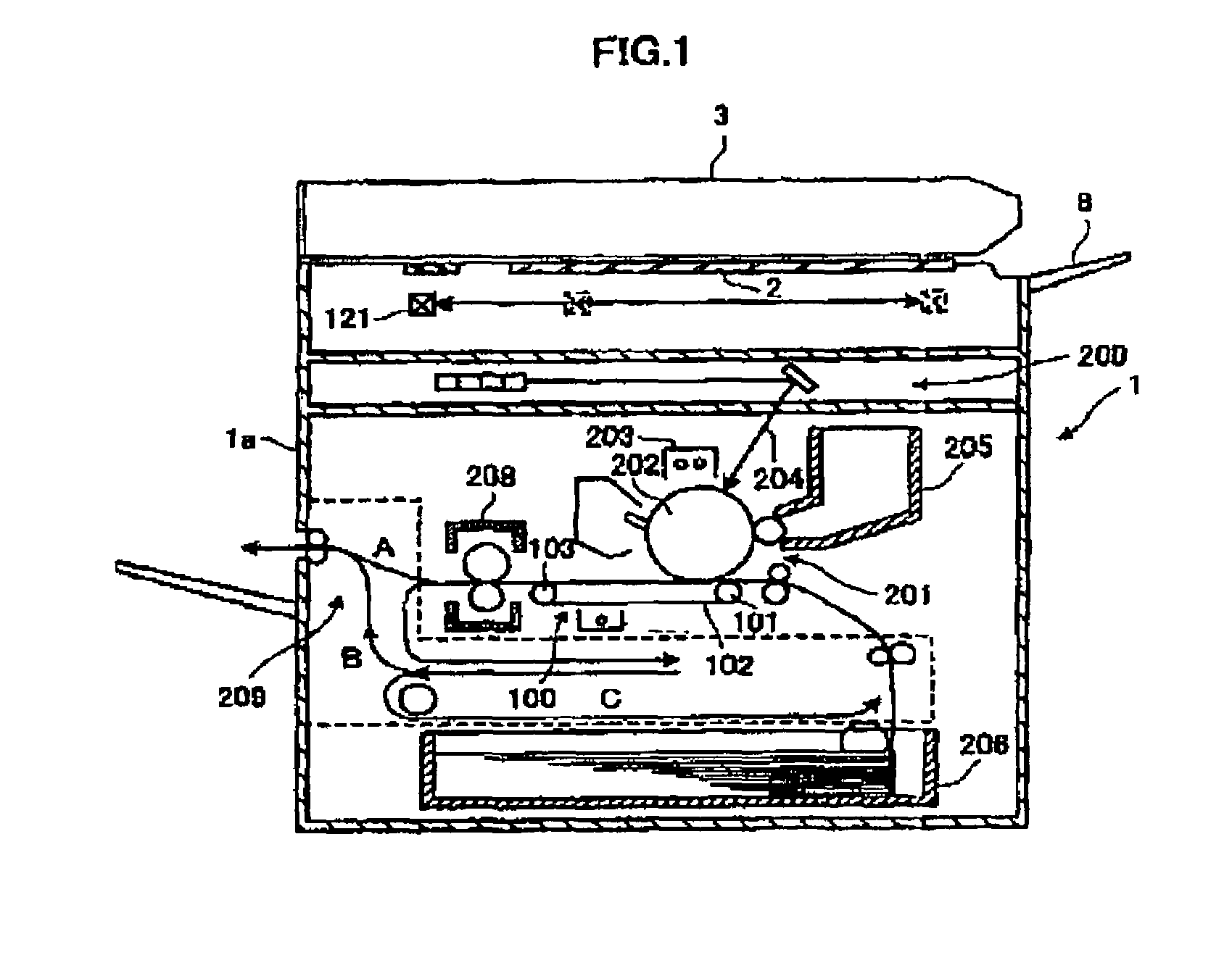
[0046]FIG. 1 shows an entire structure of a digital copy machine as an image forming apparatus to which a belt conveyance apparatus according to a first embodiment of the present invention is applied. It should be noted that the present invention is not limited to digital copy machines, and is applicable to wide variety of apparatuses if they have a belt conveyance part, such as a facsimile apparatus, a printer (including an inkjet printer), etc.
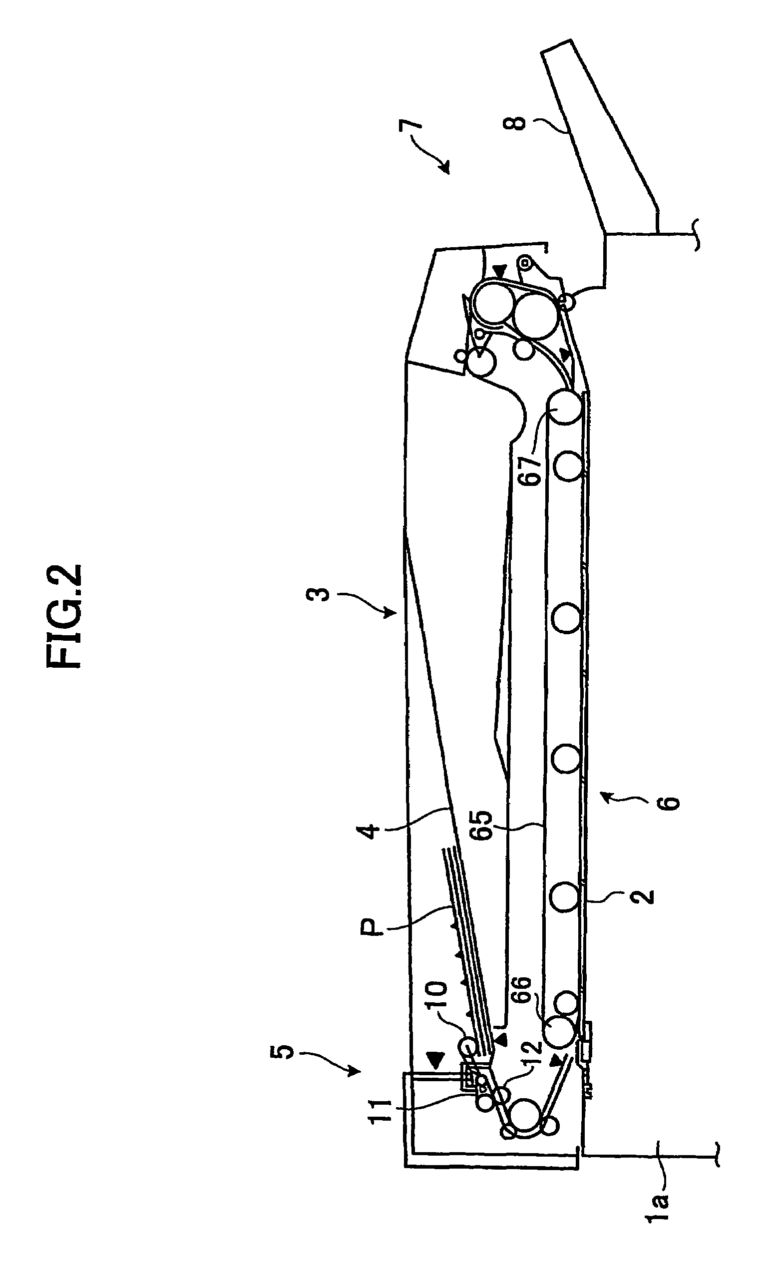
[0047]Provided on a top surface of a main body la of the digital copy machine 1 are a contact glass 2 and a slit glass having an area smaller than the contact glass 2. Additionally, an automatic document feeder 3 (hereinafter, may be abbreviated as “ADF”) is provided via a hinge mechanism (not shown) on the main body la of the digital copy machine 1 (in this example, it is placed on the contact glass 2 and slit glass). The ADF 3 is movable relative to the contact glass 2 and the slit glass so as to open or close a space above the contact gla...
second embodiment
[0069]A digital copy machine according to a second embodiment of the present invention has the same structure as the digital copy machine according to the first embodiment of the present invention except for a part of the intermediate transfer part 100, and, thus, FIGS. 1, 2, 3 and 5A are used for the description of the second embodiment and the same component parts are given the same reference numerals.
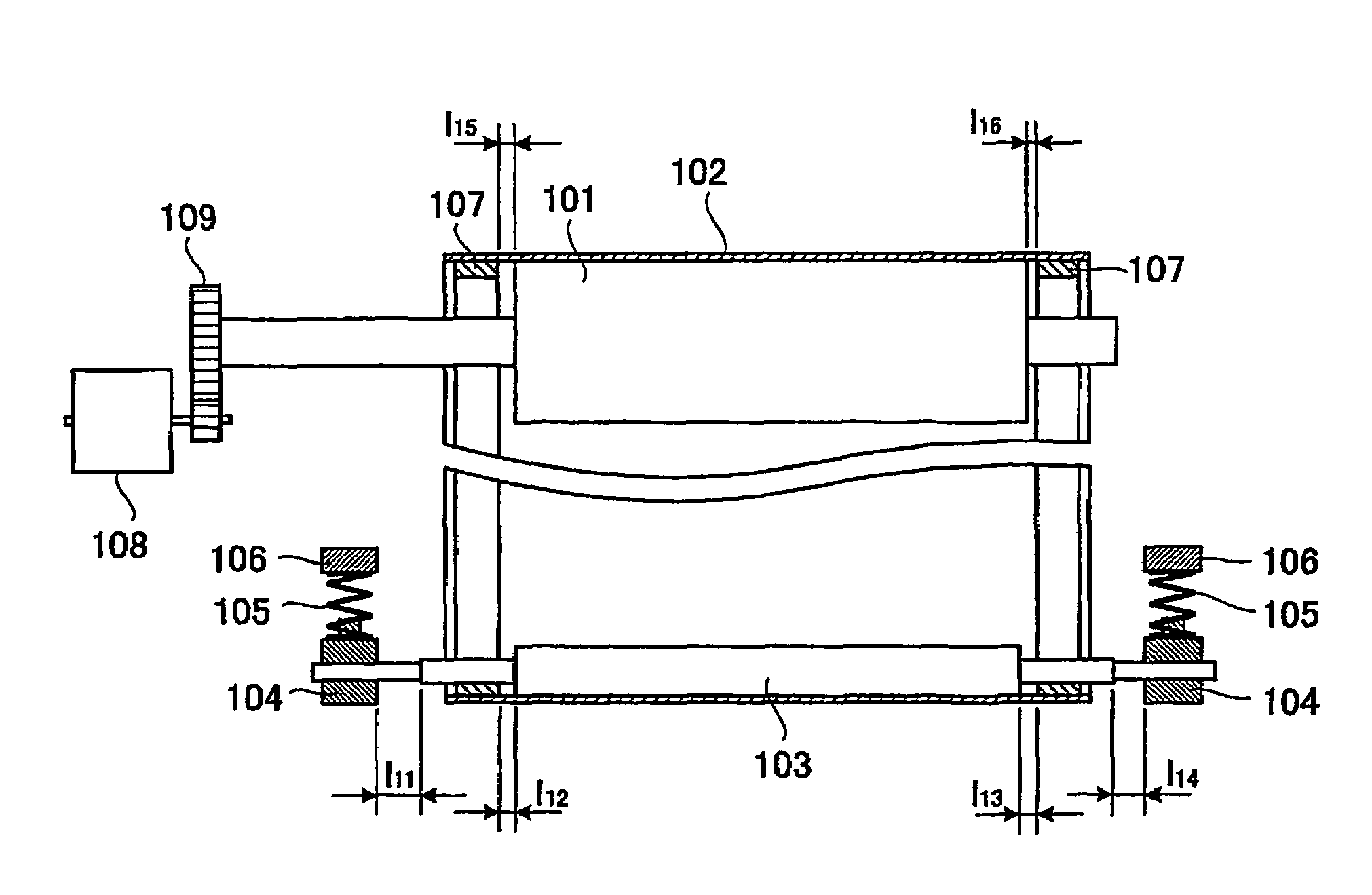
[0070]FIG. 6 shows a plan view of a part of the intermediate transfer part of the digital copy machine according to the second embodiment of the present invention.
[0071]In FIG. 6, grooves 110 for receiving the beads 107 of the intermediate transfer belt 102 are formed on the circumferential surface the intermediate transfer belt drive roller 101. Here, the grooves 110 are formed on both sides of the intermediate transfer belt drive roller 110 in the direction of width. It should be noted that the operation shown in FIG. 5A is the same as the case where the movement of the beads 107 o...
third embodiment
[0076]A digital copy machine according to a third embodiment of the present invention has the same structure as the digital copy machine according to the first embodiment of the present invention except for a part of the intermediate transfer part 100, and, thus, FIGS. 1, 2, 3 and 5A are used for the description of the third embodiment and the same component parts are given the same reference numerals.
[0077]FIG. 7 shows a plan view of a part of an intermediate transfer part of the digital copy machine according to the third embodiment of the present invention. FIGS. 8A and 8B show a part of an intermediate transfer belt drive roller having a rotational member. FIGS. 8C and 8D show a part of an intermediate transfer belt drive roller having no rotational member.
[0078]In the intermediate transfer part 100, rotational members 121 each having a tapered corner are attached to both ends of the intermediate transfer belt drive roller 101. The rotational members 121 may interfere with the b...
PUM
 Abstract
Description
Claims
Application Information
 - R&D
- Intellectual Property
- Life Sciences
- Materials
- Tech Scout
- Unparalleled Data Quality
- Higher Quality Content
- 60% Fewer Hallucinations
Browse by: Latest US Patents, China's latest patents, Technical Efficacy Thesaurus, Application Domain, Technology Topic, Popular Technical Reports.
© 2025 PatSnap. All rights reserved.Legal|Privacy policy|Modern Slavery Act Transparency Statement|Sitemap|About US| Contact US: help@patsnap.com


