Light-emitting diode
a technology of light-emitting diodes and diodes, which is applied in the direction of basic electric elements, electrical equipment, and semiconductor devices, can solve the problems of leakage of light-emitting resins, pass through light-emitting resins, etc., and achieve the effect of high light-emitting efficiency and minimal light-wastag
- Summary
- Abstract
- Description
- Claims
- Application Information
AI Technical Summary
Benefits of technology
Problems solved by technology
Method used
Image

Examples
first embodiment
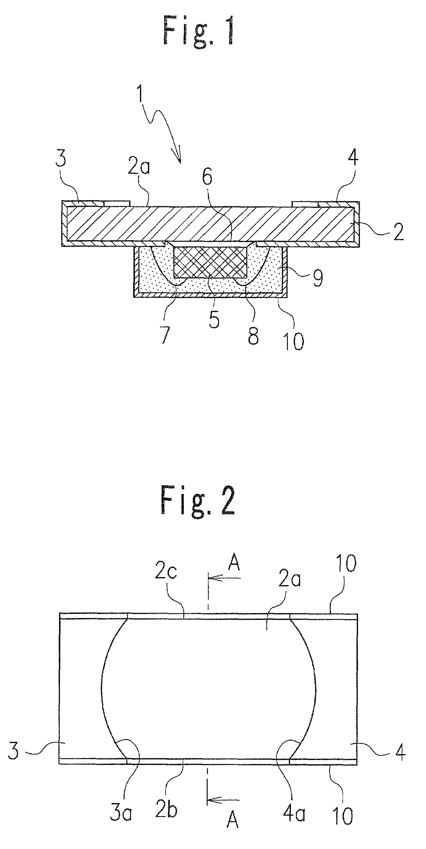
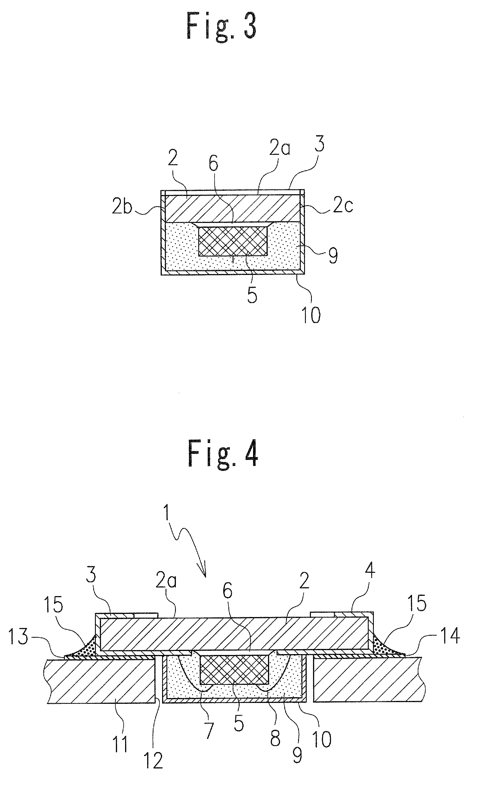
[0023]As shown in FIGS. 1 to 3, an LED 1 according to the present invention includes: a light-transmitting substrate 2 made of insulating material; a pair of electrodes 3 and 4 formed on a surface of the light-transmitting substrate 2 by vapor deposition, etching, printing, plating or the like; a light-emitting element 5 bonded to a substantially central position of the upper surface of the light-transmitting substrate 2 with a transparent adhesive 6; metal wires 7 and 8 for electrically connecting the light-emitting element 5 to the electrodes 3 and 4, respectively; and a light-transmitting resin 9 that seals the metal wires 7 and 8 and the light-emitting element 5.
[0024]A glass epoxy resin substrate, for example, is used as the light-transmitting substrate 2. Each of the electrodes 3 and 4 extends from the upper surface 2 to the lower surface 2a via the left or right side surface of the light-transmitting substrate 2. As shown in FIG. 2, the electrodes 3 and 4 have curved edges 3a...
second embodiment
[0029]As in the preceding embodiment, in the LED 20 light emitted from the light-emitting element 5 is reflected on the reflecting layer 10 that covers the entire outer surface of the light-transmitting resin 9. The reflected light passes through the light-transmitting resin 9, the transparent adhesive 6, and the light-transmitting substrate 2 and is then emitted from the lower surface 2a of the light-transmitting substrate 2. When the reflected light passes through the transparent adhesive 6, the light is irregularly diffused due to the presence of the light scattering agent 21 included therein, and thus, the luminance of light emitted from the lower surface 2a of the light-transmitting substrate 2 can be improved.
[0030]In place of the light-scattering agent 21, a fluorescent agent may be included in the transparent adhesive 6, or both of the agents may be included therein. In the case where the fluorescent agent is included, the wavelength of the reflected light is converted thro...
third embodiment
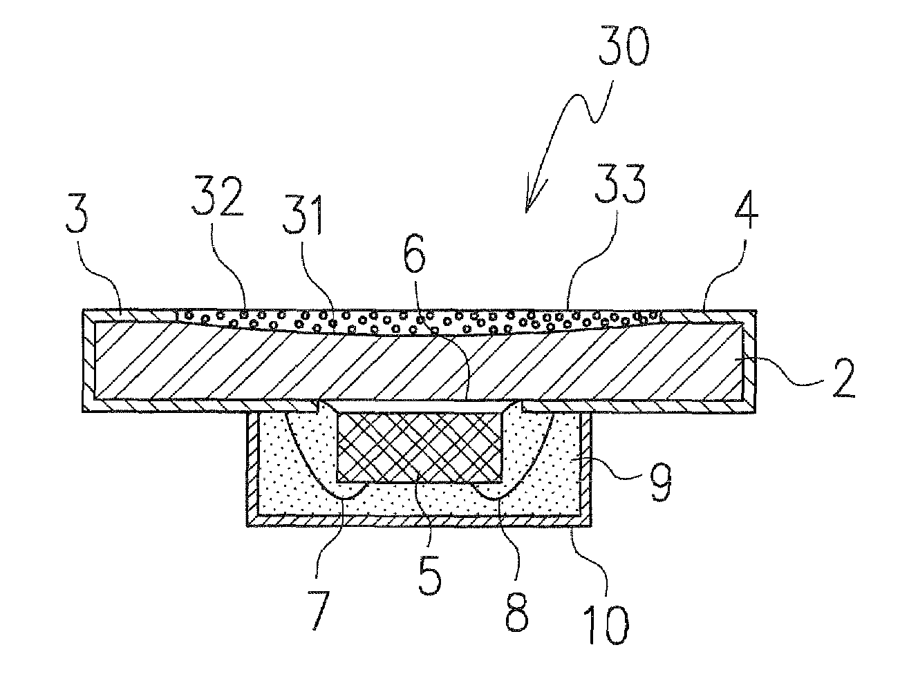
[0033]As in the embodiments described above, in the LED 30 light emitted from the light-emitting element 5 is reflected on the reflecting layer 10 that covers the outer surface of the light-transmitting resin 9. The reflected light passes through the light-transmitting resin 9, the transparent adhesive 6, and the light-transmitting substrate 2 and is then emitted from the lower surface 2a of the light-transmitting substrate 2. Moreover, when the reflected light is emitted from the lower surface 2a of the light-transmitting substrate 2, the recess 31 provided in the light-transmitting substrate 2 produces a light-gathering effect similar to that of a concave lens, and the luminance of the light emitted from the lower surface 2a of the light-transmitting substrate 2 is improved by the scattering effect of the light-scattering agent 32 included in the transparent resin 33.
[0034]In place of the light-scattering agent 32, a fluorescent agent may be included in the transparent resin 33 o...
PUM
 Abstract
Description
Claims
Application Information
 - R&D Engineer
- R&D Manager
- IP Professional
- Industry Leading Data Capabilities
- Powerful AI technology
- Patent DNA Extraction
Browse by: Latest US Patents, China's latest patents, Technical Efficacy Thesaurus, Application Domain, Technology Topic.
© 2024 PatSnap. All rights reserved.Legal|Privacy policy|Modern Slavery Act Transparency Statement|Sitemap