Seating area adjuster
a technology for adjusting apparatus and seat, which is applied in the direction of chairs, movable seats, transportation and packaging, etc., can solve the problems of increasing spring size, increasing manufacturing cost and weight of the adjuster, and difficulty in equalizing the movement amount of the roller with the movement amount of the lever
- Summary
- Abstract
- Description
- Claims
- Application Information
AI Technical Summary
Benefits of technology
Problems solved by technology
Method used
Image
Examples
first embodiment
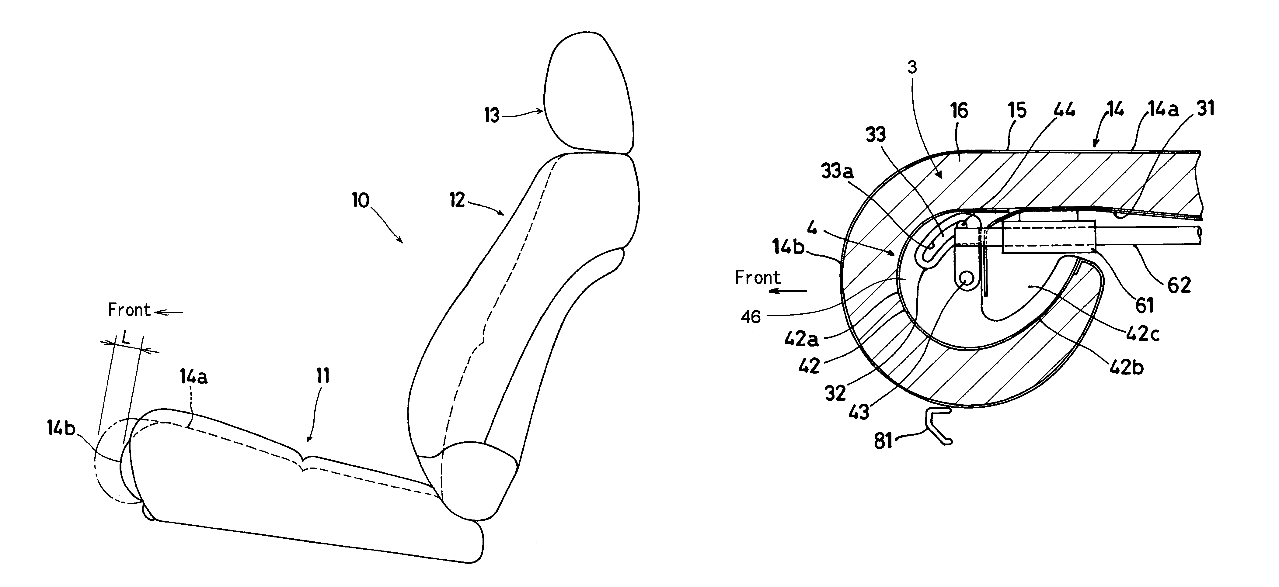
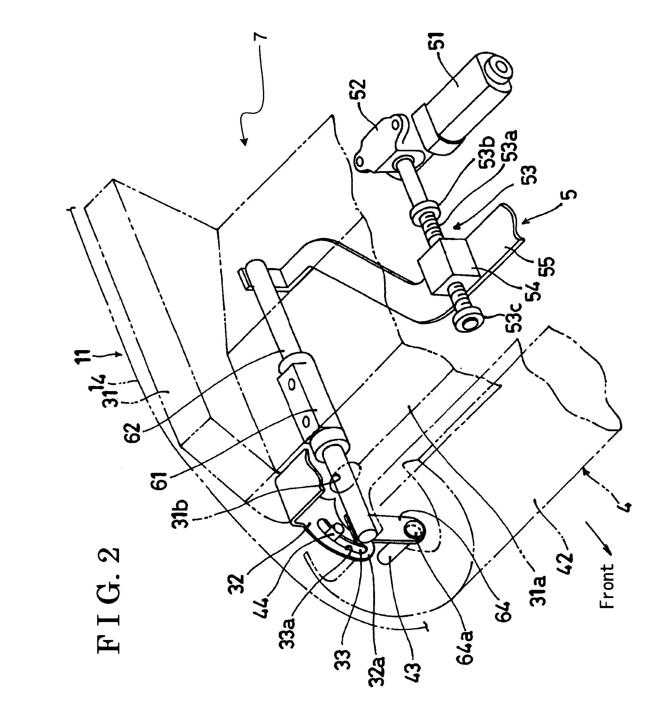
[0020]a seating area adjuster 7 (see FIG. 2, hereinafter, referred to as an adjuster 7) of a seat according to the present invention will be explained hereinbelow with reference to FIGS. 1-6.
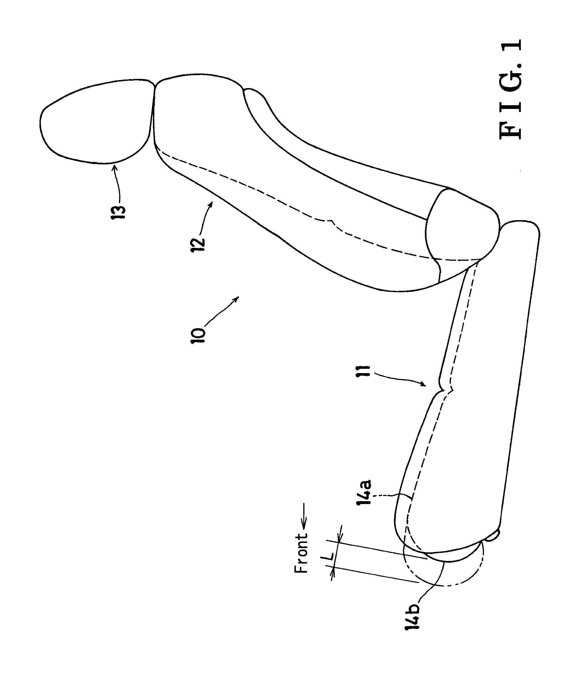
[0021]As illustrated in FIG. 1, a seat 10 mainly includes a seat cushion 11, a seatback 12, and a headrest 13. The adjuster 7 according to the present invention includes a basic configuration applicable to any one of the seat cushion 11, the seatback 12, and the headrest 13. However, an example of the adjuster 7 applied to the seat cushion 11 will be given in the following explanation.
[0022]The configuration of the adjuster 7 applied to the seat cushion 11 is illustrated in FIGS. 1-5. The seat cushion 11 includes a seating member 14 which comes in contact with a user at a seating surface 14a. The adjuster 7 includes the configuration of adjusting a position of an end portion 14b of the seating surface 14a at any location between a fully retracted position indicated by a solid line and an L-lengt...
second embodiment
[0040]A second embodiment of the present invention will be explained hereinafter. An adjuster 107 according to the present invention is illustrated in FIGS. 7 and 8. The same structure as described in the aforementioned embodiment is not repeatedly explained. A link mechanism 162 is used as a movement mechanism 105. The link mechanism 162 is called “X link” in a mechanistic field and is configured of four link elements. The link mechanism 162 is activated by means of an operation of an expansion and contraction device unit 151. More specifically, the link mechanism 162 supports a rotation shaft 143 of a drum 104 and moves the rotation shaft 143 in the back and forth direction as well as the rod 62 of the first embodiment of the present invention. The link mechanism is not limited to the X link. The present invention is applicable as long as the link mechanism moves the rotation shaft 143 in the back and forth direction. By use of a high quality finished link mechanism which is conve...
PUM
 Abstract
Description
Claims
Application Information
 - R&D
- Intellectual Property
- Life Sciences
- Materials
- Tech Scout
- Unparalleled Data Quality
- Higher Quality Content
- 60% Fewer Hallucinations
Browse by: Latest US Patents, China's latest patents, Technical Efficacy Thesaurus, Application Domain, Technology Topic, Popular Technical Reports.
© 2025 PatSnap. All rights reserved.Legal|Privacy policy|Modern Slavery Act Transparency Statement|Sitemap|About US| Contact US: help@patsnap.com


