Electronic level gage assembly

a technology assembly, which is applied in the direction of liquid/fluent solid measurement, instruments, machines/engines, etc., can solve the problems of electronic level gage components failing or needing servicing

Active Publication Date: 2009-11-03
JOGLER
View PDF18 Cites 20 Cited by
  • Summary
  • Abstract
  • Description
  • Claims
  • Application Information

AI Technical Summary

Benefits of technology

[0012]Another embodiment of the invention provides a method for remotely determining a fluid level in a tank with a magnetostrictive wave guide probe. The method is carried out by isolating the wave guide probe from an inside of the tank by positioning a thermowell in the tank and positioning the wave guide probe inside the thermowell. A fluid interface seeking float carrying magnets is positioned on the outside of the thermowell, and the wave guide probe is actuated to remotely determine to the position of the float. Where the inside of the tank is isolated from the outside of the tank by the thermowell, the wave guide probe can be removed from the tank without breaking seal on the tank.

Problems solved by technology

A disadvantage is that components of an electronic gage can fail or require servicing, necessitating their removal.

Method used


Image

  • Electronic level gage assembly
  • Electronic level gage assembly
  • Electronic level gage assembly

Examples


Embodiment Construction

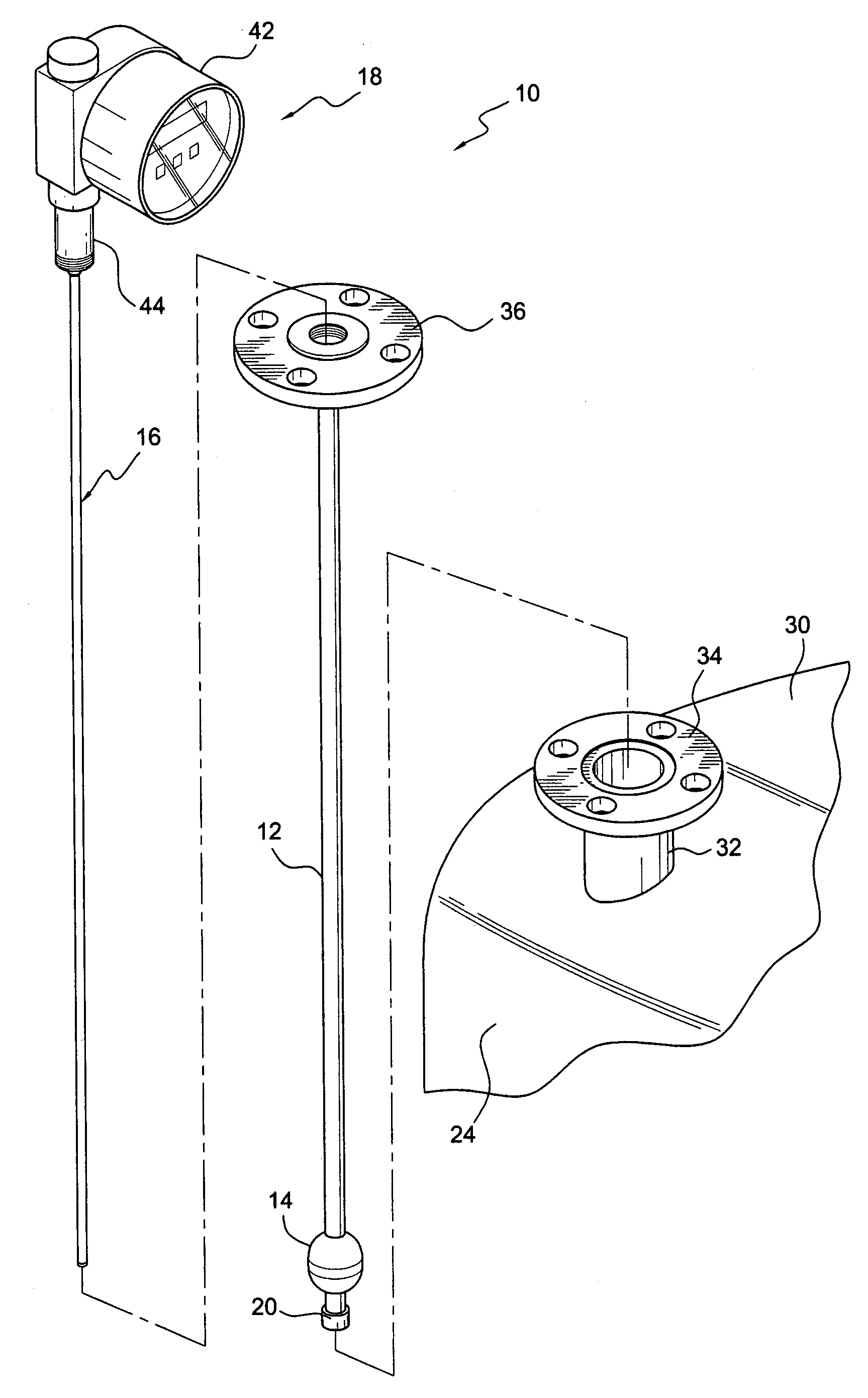
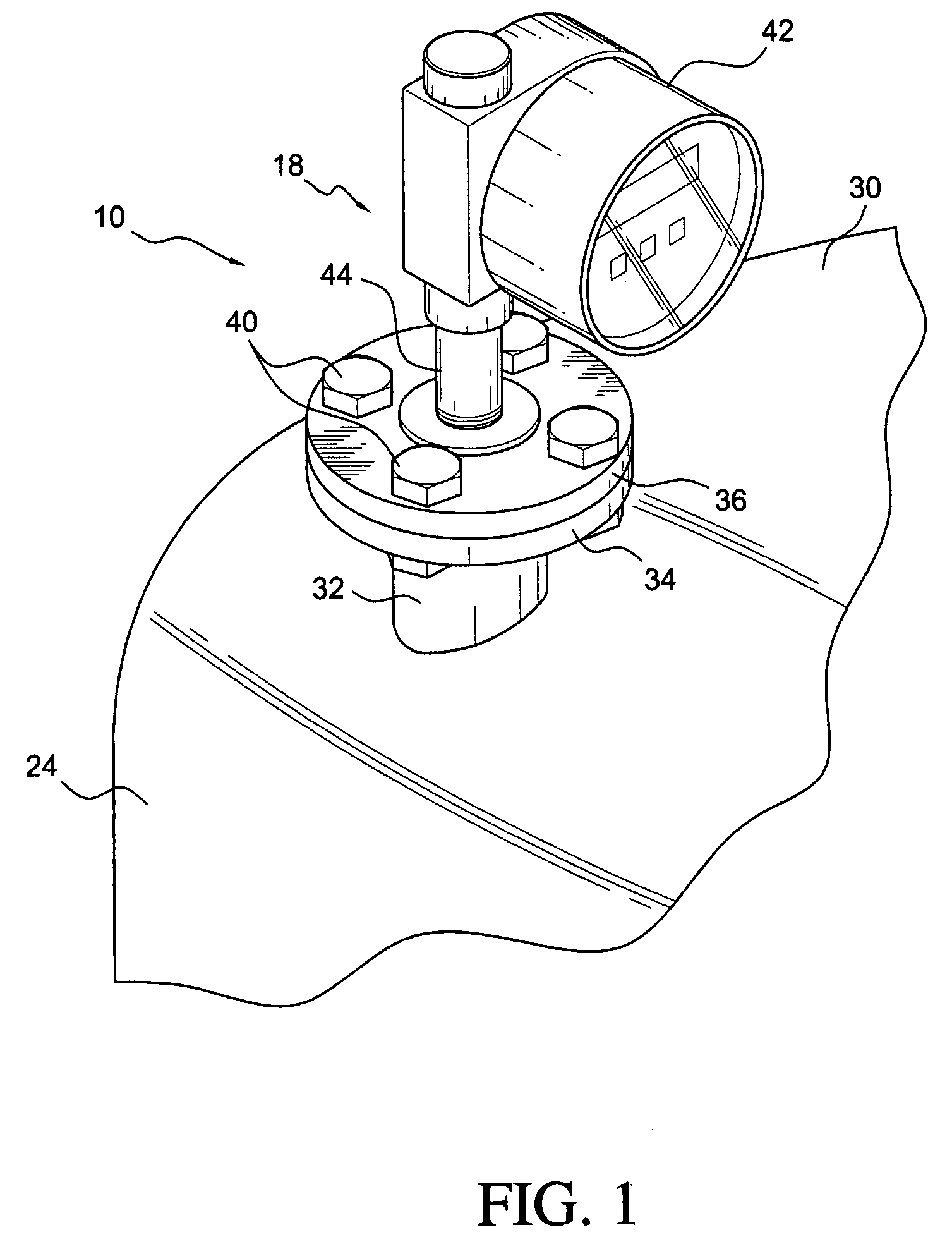
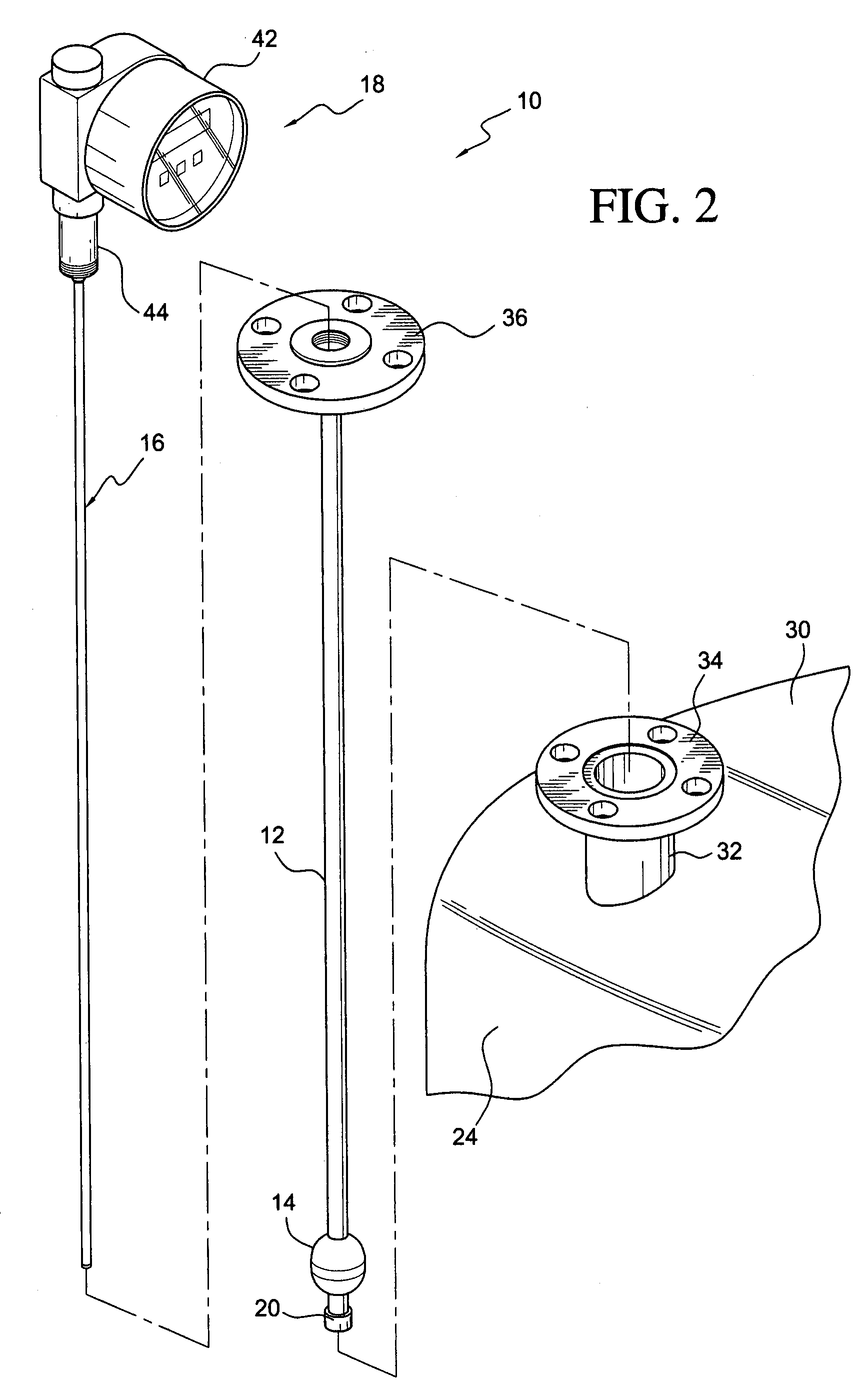
[0020]In one embodiment of the invention, there is provided an apparatus 10 comprising a nonmagnetic outer thermowell tube 12, a magnetic annularly shaped fluid-interface-seeking float 14, a wave guide probe 16, and an electronics assembly 18. The nonmagnetic outer tube has an upper end and a lower end and an end cover 20 positioned sealingly on its lower end. The float is slidably positioned on the outer tube. The wave guide probe is positioned in the outer tube. The electronics assembly is operably associated with the wave guide probe for actuating the wave guide probe and producing an electrical output signal representative of a location of the float on the outer tube. The apparatus can be usefully employed to electronically measure liquid levels 22 in a tank 24.

[0021]The wave guide probe is generally tubular, and preferably has an outside diameter in the range of from about 0.25 to about 0.5 inches. The small diameter permits it to be deployed in a small inside diameter outer tu...


PUM


Abstract

A thermowell extends downwardly into tank liquids from the roof of the tank. A magnetostrictive wave guide probe is positioned on the inside of the thermowell and a magnetic float is slidably positioned on the outside of the thermowell. The probe is connected to a head unit containing the necessary electronics for operability which is positioned outside of the tank. The position of the float, and thus the liquid level, is remotely sensed by the probe, and the probe can be removed from the thermowell if necessary without breaking the seal of the tank.

Description

RELATED APPLICATIONS[0001]This application is a continuation in part of application Ser. No. 11 / 590,108, filed Oct. 31, 2006, the disclosure of which is incorporated by reference herein.FIELD OF THE INVENTION[0002]In certain aspects, this invention relates to an electronic level gage assembly for measuring liquid levels in tanks. In other aspects, this invention relates to improvements in level gages for liquids and methods for measuring liquid levels in tanks.BACKGROUND OF THE INVENTION[0003]Level gages are used to determine liquid levels in tanks. A sight glass positioned on the outside of the tank is suitable for many applications. Other types of level gages for tanks generally rely on electronics and / or a float for operability, and can have components positioned inside or outside of the tank.[0004]An advantage of an electronic gage is that the level reading can be instantaneously transmitted to a remote location for a continuous level readout. The electronic level signal can als...

Claims


Application Information

Patent Timeline
Patent Type & Authority Patents(United States)
IPC IPC(8): G01F23/00
CPCG01F23/2963G01F23/72G01F23/68
Inventor SKINNER, JEFFREY M.
Owner JOGLER
Why Eureka
Try Eureka