
Device for measuring filter pressure loss

a technology for pressure loss measurement and apparatus, which is applied in the direction of auxillary pretreatment, sedimentation settling tanks, separation processes, etc., can solve the problems of difficulty in finely regulating the rotation speed, difficulty in subjecting numerous filters to pressure loss measurement, etc., and achieve reliable and convenient measurement of filter pressure loss

Active Publication Date: 2009-10-27
NGK INSULATORS LTD
View PDF26 Cites 2 Cited by
  • Summary
  • Abstract
  • Description
  • Claims
  • Application Information

AI Technical Summary

Benefits of technology

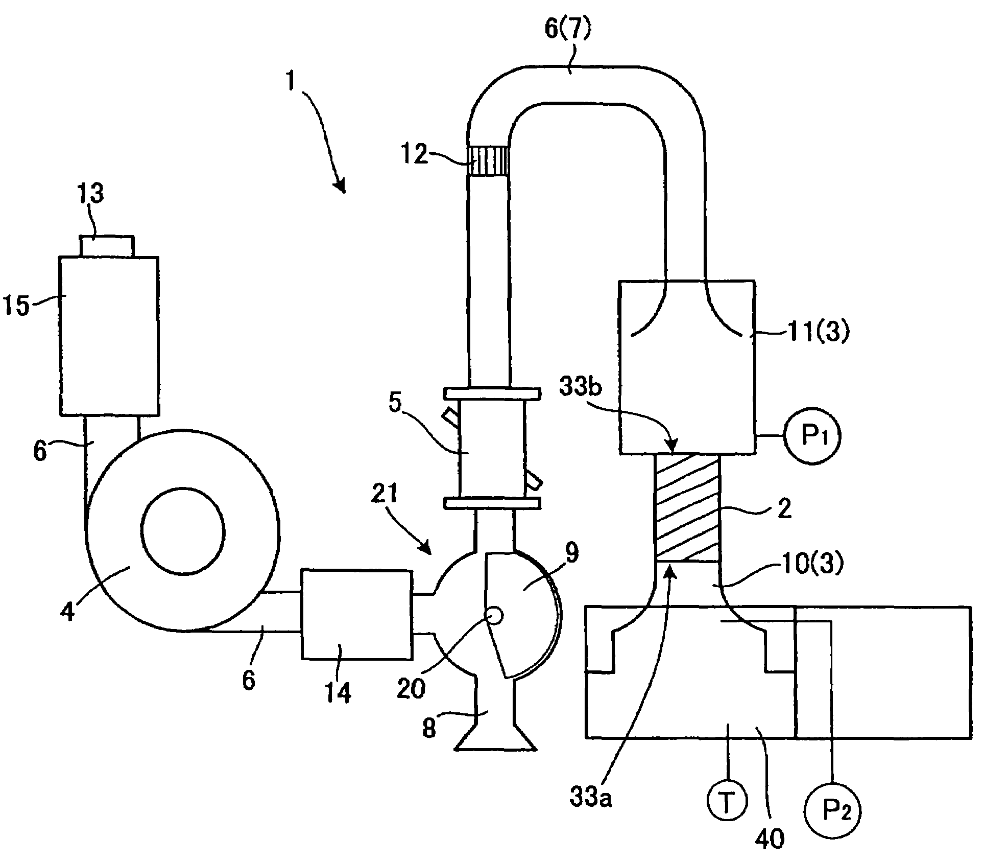
[0008]In view of the problems involved in the aforementioned conventional techniques, an object of the present invention is to provide an apparatus for measuring pressure loss in a filter, which achieves reliable and convenient measurement of filter pressure loss at a constant flow rate.

Problems solved by technology

Therefore, this apparatus cannot be employed for subjecting numerous DPFs to pressure loss measurement at a constant flow rate, thereby evaluating variations in DPF pressure loss.
However, in the case where numerous filters are required to be subjected to pressure loss evaluation in mass production equipment, difficulty is encountered in finely regulating the rotation speed of a blower for different individual filters within a short period of time, and in obtaining reliable measurement results with few errors.
In addition, difficulty in finely regulating the blower rotation speed requires an intricate measurement process, which poses a problem in that difficulty is encountered in subjecting numerous filters to pressure loss measurement.Patent Document 1: Japanese Patent No. 2807370Non-Patent Document 1: [online], SuperFlow Corporation, [Searched on Dec. 12, 2003], Internet

Method used


Image

  • Device for measuring filter pressure loss
  • Device for measuring filter pressure loss
  • Device for measuring filter pressure loss

Examples


example

Example

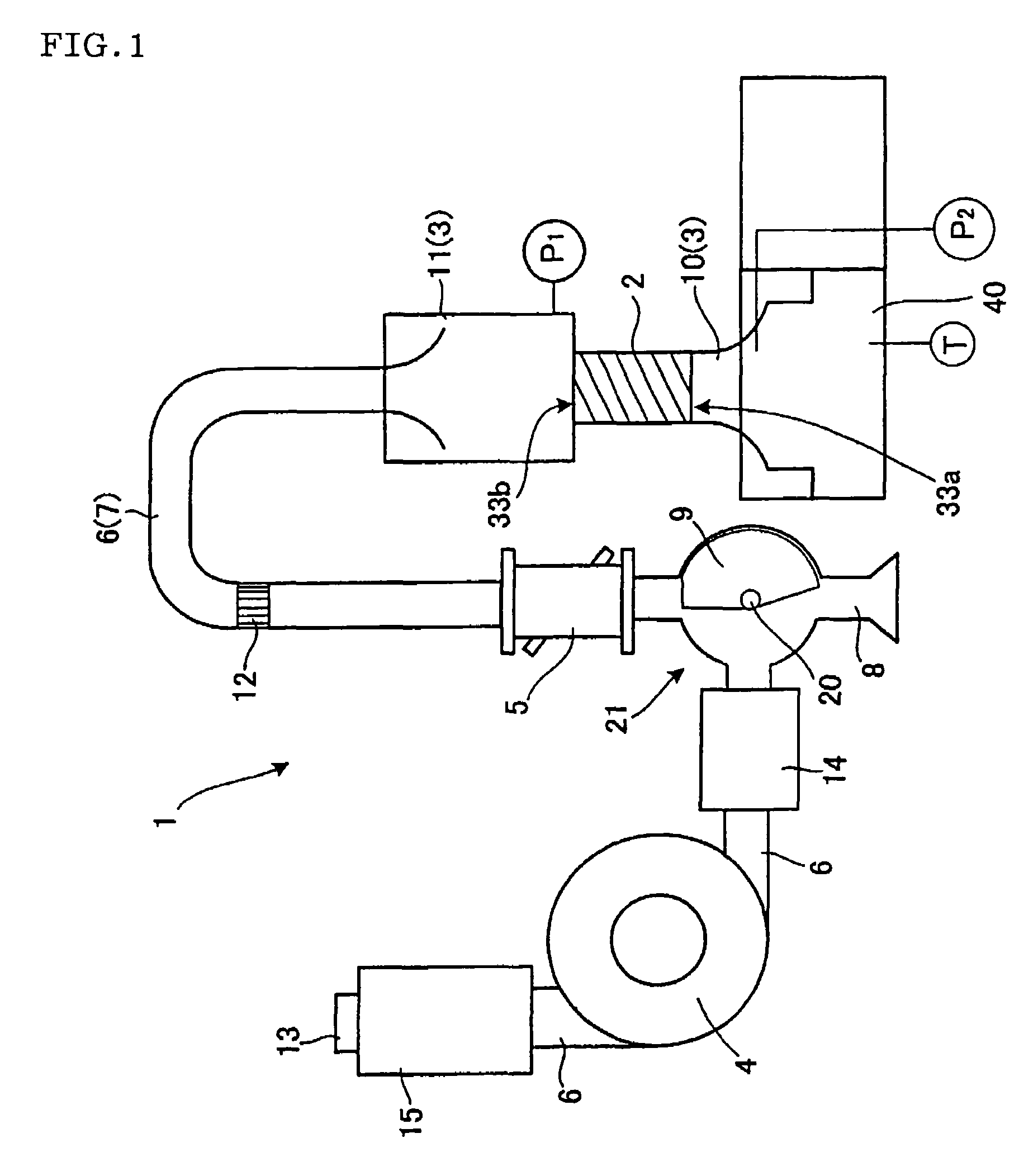
[0044]One cylindrical DPF (dimensions: 144 mmφ (outer diameter)×155 mm (total length)) was subjected to pressure loss measurement by means of the pressure loss measuring apparatus 1 shown in FIG. 1. The blower 4 of the pressure loss measuring apparatus 1 was a turbo blower having a discharge pressure of 20 kPa at a flow rate of 20 Nm3 / min, and the flow rate was regulated to 9 Nm3 / min. The DPF was also subjected to pressure loss measurement through wind tunnel testing by means of a wind tunnel for reference evaluation. FIG. 5 shows a graph in which pressure loss values (kPa) as measured by means of the wind tunnel are plotted against pressure loss values (kPa) as measured by means of the pressure loss measuring apparatus.

Evaluation

[0045]The absolute error of the pressure loss values (kPa) as measured by means of the pressure loss measuring apparatus (i.e., measurement values) against the pressure loss values (kPa) as measured by means of the wind tunnel (i.e., reference values...


PUM

PropertyMeasurementUnit
discharge pressureaaaaaaaaaa

Abstract

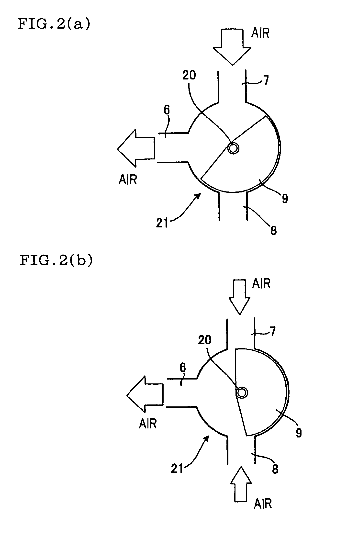
Provided is an apparatus 1 for measuring pressure loss in a filter 2, which apparatus includes filter holding means 3; fluid passing means; flow rate measuring means; pressure loss measuring means; and a flow path 6 which connects the four means such that a fluid can pass between the means. The apparatus further includes flow rate regulating means having a mainstream path 7; a tributary path 8 which is branched from the mainstream path 7 and communicates with the outside; and one or more flow path opening / closing members 9 capable of, in conjunction with the level of the fluid flow rate as measured through the flow rate measuring means, opening or closing the mainstream path 7 or the tributary path 8 such that the flow path opening ratio of each of the paths varies continuously or intermittently. The apparatus achieves reliable and convenient measurement of pressure loss with the flow rate of the fluid which passes through the filter 2 being maintained at a constant level by the flow rate regulating means.

Description

TECHNICAL FIELD[0001]The present invention relates to an apparatus for measuring pressure loss in a filter, and more particularly to an apparatus for measuring pressure loss in a filter, which achieves reliable and convenient measurement of filter pressure loss at a constant flow rate.BACKGROUND ART[0002]Diesel particulate filters (DPFs) are widely employed as filters for trapping and removing a particulate matter contained in a soot-containing fluid such as exhaust gas discharged from a diesel engine. A DPF has an inflow end face through which exhaust gas enters, and an outflow end face through which exhaust gas is discharged, and has a honeycomb structure including a plurality of cells which are formed of porous partition walls having numerous pores (through holes), in which the inflow end faces of predetermined cells and the outflow end faces of the remaining cells are alternately sealed. When particulate matter-containing exhaust gas enters into a cell through its inflow end fac...

Claims


Application Information

Patent Timeline
Patent Type & Authority Patents(United States)
IPC IPC(8): B01D46/00G01N15/08B01D46/42B01D46/44F01N3/02G01N15/14
CPCB01D46/0086B01D46/4272B01D46/446G01N2015/1493B01D2279/30
Inventor SAKASHITA, SATOSHITAKAHASHI, MITSUO
Owner NGK INSULATORS LTD
Learn More