
Method for obtaining an identifier of a monitored device

a technology of identifying and monitoring devices, applied in the direction of digital transmission, data switching networks, instruments, etc., can solve the problems of automatic hardware installation software limiting its ability to adapt to new devices, software that operates the devices to not be configured, disadvantages and deficiencies of these attempts, etc., to maximize communication, maximize the effectiveness of communication means, and maximize the effect of established communication means of interfacing devices

Inactive Publication Date: 2009-10-20
RICOH KK
View PDF59 Cites 0 Cited by
  • Summary
  • Abstract
  • Description
  • Claims
  • Application Information

AI Technical Summary

Benefits of technology

This method enables effective communication and configuration of hardware devices across different manufacturers and models, enhancing adaptability and usability by leveraging manufacturer-specific and universal communication protocols, ensuring devices can operate cooperatively and be monitored efficiently.

Problems solved by technology

When hardware devices initially interface with one another, it is common for the software that operates the devices to not be configured to allow cooperative operation.
However, there are some apparent disadvantages and deficiencies of these attempts.
One disadvantage is that automatic hardware installation software is limiting in its ability to adapt to new devices or to new manufacturers that were not specifically programmed into the software.
In the prior art, if the controlling device does not recognize the specific model of the interfacing device, automatic configuration is not possible.
In other words, in the prior art, if the controlling device is not programmed to anticipate the model of an interfacing device, then automatic hardware configuration will not be successful.
Another disadvantage of the prior art is that the controlling device is unable to partially configure hardware devices if the particular model of the interfacing device cannot be identified.
In other words, if a controlling device cannot identify a specific model of the interfacing device, then the interfacing device will not be configured to operate cooperatively.
This results in the unconfigured interfacing device being inoperable and essentially useless.
However, it has been difficult for a controlling device to communicate with various interfacing devices on a network given the different communication means between manufacturers and models of interfacing devices.
This disadvantage is problematic, as administrators of networks are unable to obtain crucial information about the performance and efficiency of interfacing devices on a network.

Method used


Image

  • Method for obtaining an identifier of a monitored device
  • Method for obtaining an identifier of a monitored device
  • Method for obtaining an identifier of a monitored device

Examples


Embodiment Construction

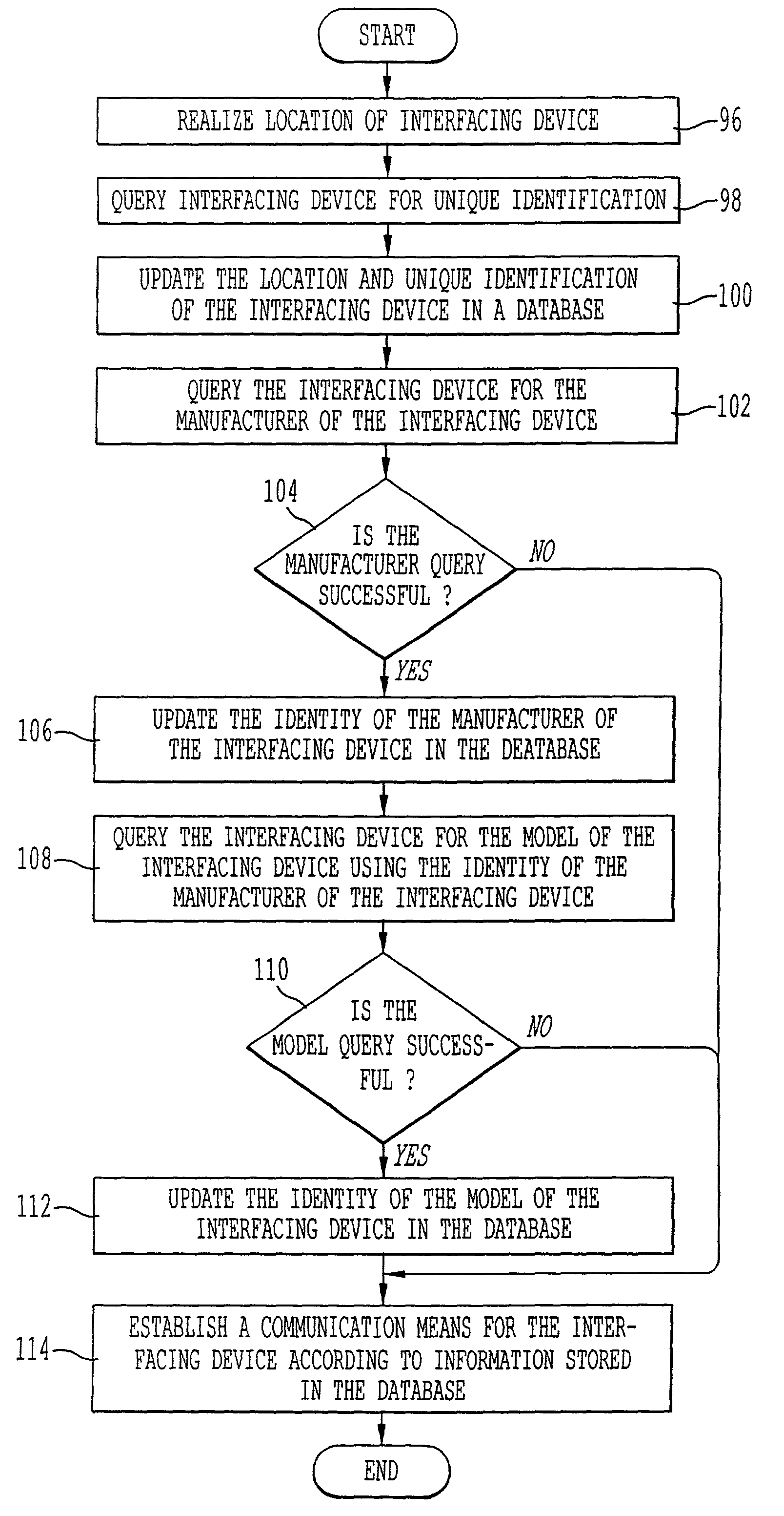
[0063]Embodiments of the present invention relate to a method for a controlling device to establish a communication means for an interfacing device. The method comprises the following steps: Realizing the location of the interfacing device. Updating in the first database the location of the interfacing device. Querying the interfacing device for the identity of the manufacturer of the interfacing device. Updating in the first database the manufacturer of the interfacing device, if the querying for the manufacturer of the interfacing device is successful. Querying the interfacing device, utilizing the identity of the manufacturer, for the identity of the model of the interfacing device, if the querying of the interfacing device for the identity of the manufacturer of the interfacing device is successful. Updating in the first database the identity of the model of the interfacing device, if the query for the identity of the model of the interfacing device is successful. Establishing a...


PUM


Abstract

The present invention relates to determining the unique identification of an interfacing device. The interfacing device is first queried utilizing the hierarchical relationship of the interfacing devices communication means to acquire the unique identification. If this querying is unsuccessful, then a standard communication means (i.e. SNMP) is utilized to acquire the unique identification from the interfacing device. If use of the standard communication means is also unsuccessful, then assign a random code for the unique identification of the interfacing device.

Description

CROSS REFERENCES TO RELATED APPLICATIONS[0001]This application is related to commonly owned co-pending U.S. patent application Ser. No. 09 / 756,120, filed Jan. 9, 2001, entitled “Method and System of Remote Support of Device Using Email,” which is incorporated herein by reference.BACKGROUND OF INVENTION[0002]1. Field of Invention[0003]The present invention is related to monitoring, configuration or installation of hardware on a computer system.[0004]2. Discussion of the Background[0005]In general, computer systems include hardware and software. Hardware is the actual physical computing machinery, while software is the list of instructions to operate the hardware. Typically, computer systems will include a variety of hardware devices that interface with one another. When hardware devices interface with one another, it is necessary for the software which operates the hardware to be configured to allow communication between the hardware devices, so that the hardware devices can operate ...

Claims


Application Information

Patent Timeline
Patent Type & Authority Patents(United States)
IPC IPC(8): G06F15/16H04L12/24H04L12/26
CPCH04L12/2602H04L43/00H04L41/0853H04L41/0213H04L43/0817
Inventor MOTOYAMA, TETSUROFONG, AVERY
Owner RICOH KK
Learn More