
Mono-Crutch for lower leg disability

a technology for lower legs and mono-crutches, which is applied in the field of partial crutches, can solve the problems of inconvenient use, inconvenient use, and inability to carry,

Inactive Publication Date: 2009-10-13
MOBILITY SOLUTIONS
View PDF22 Cites 21 Cited by
  • Summary
  • Abstract
  • Description
  • Claims
  • Application Information

AI Technical Summary

Benefits of technology

"The present invention is a mono-crutch for lower leg disability. It consists of an upper leg support, a lower leg support, and a ground contact member. The upper leg support attaches to the user's upper leg portion and has a pair of thigh pad portions that are staggered relative to each other. The lower leg support attaches to the user's lower leg portion and has a contoured support for cradling the user's lower leg portion. The ground contact member contacts a ground surface and is attached to the upper leg support. The invention allows users to walk and stand with support while maintaining their natural gait."

Problems solved by technology

Frequently, individuals will injure or otherwise experience a debilitation of their lower extremities.
For instance, a user may sprain an ankle or break a bone in his / her foot.
Additionally, such ambulatory devices are frequently used by below knee (BK) amputees who can't afford or are otherwise between prosthetics.
Both are awkward and require (predominantly) both hands.
Typically, the incapacitated lower leg must be held elevated by the users, with bending at the knee, causing fatigue.

Method used


Image

  • Mono-Crutch for lower leg disability
  • Mono-Crutch for lower leg disability
  • Mono-Crutch for lower leg disability

Examples


first embodiment

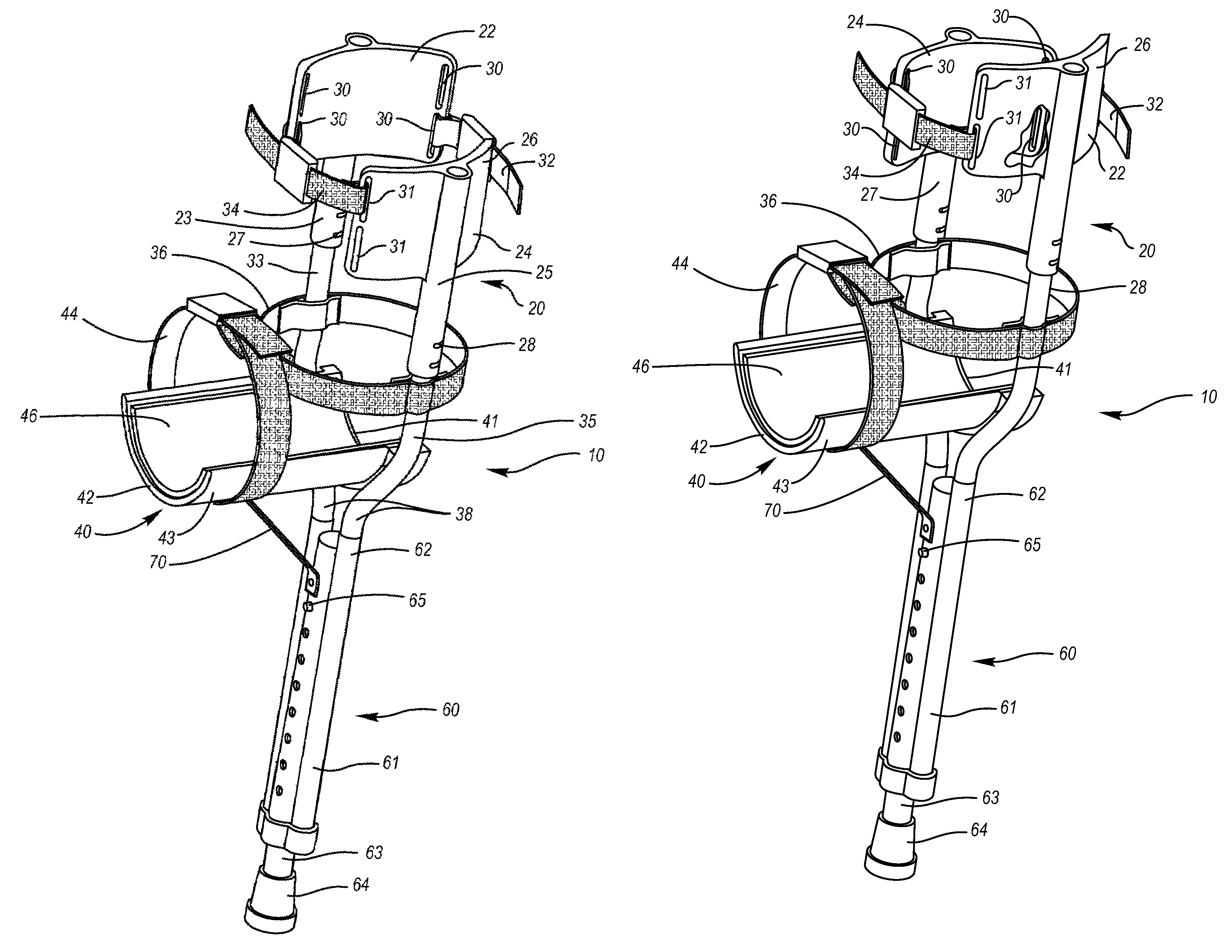
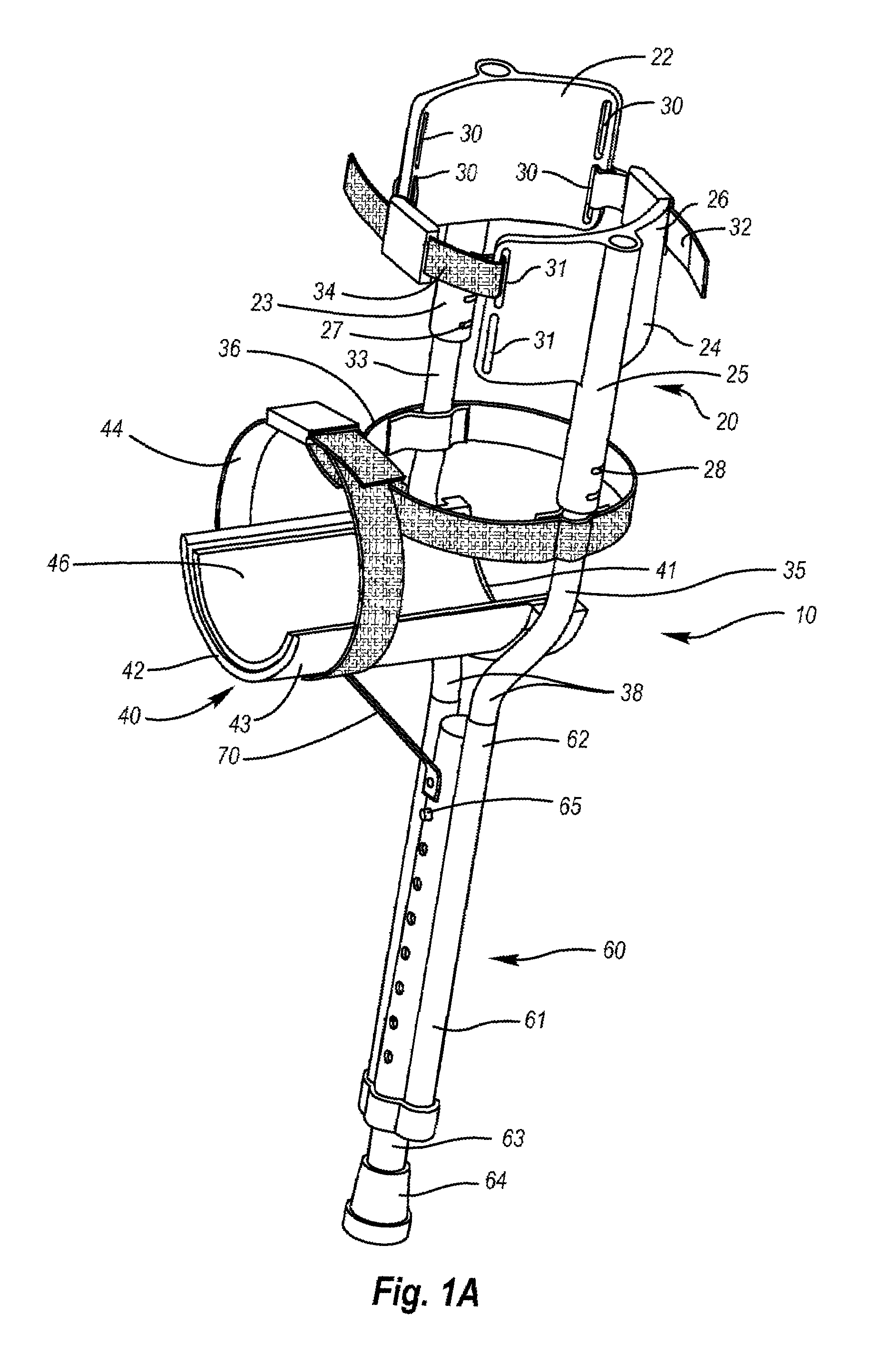
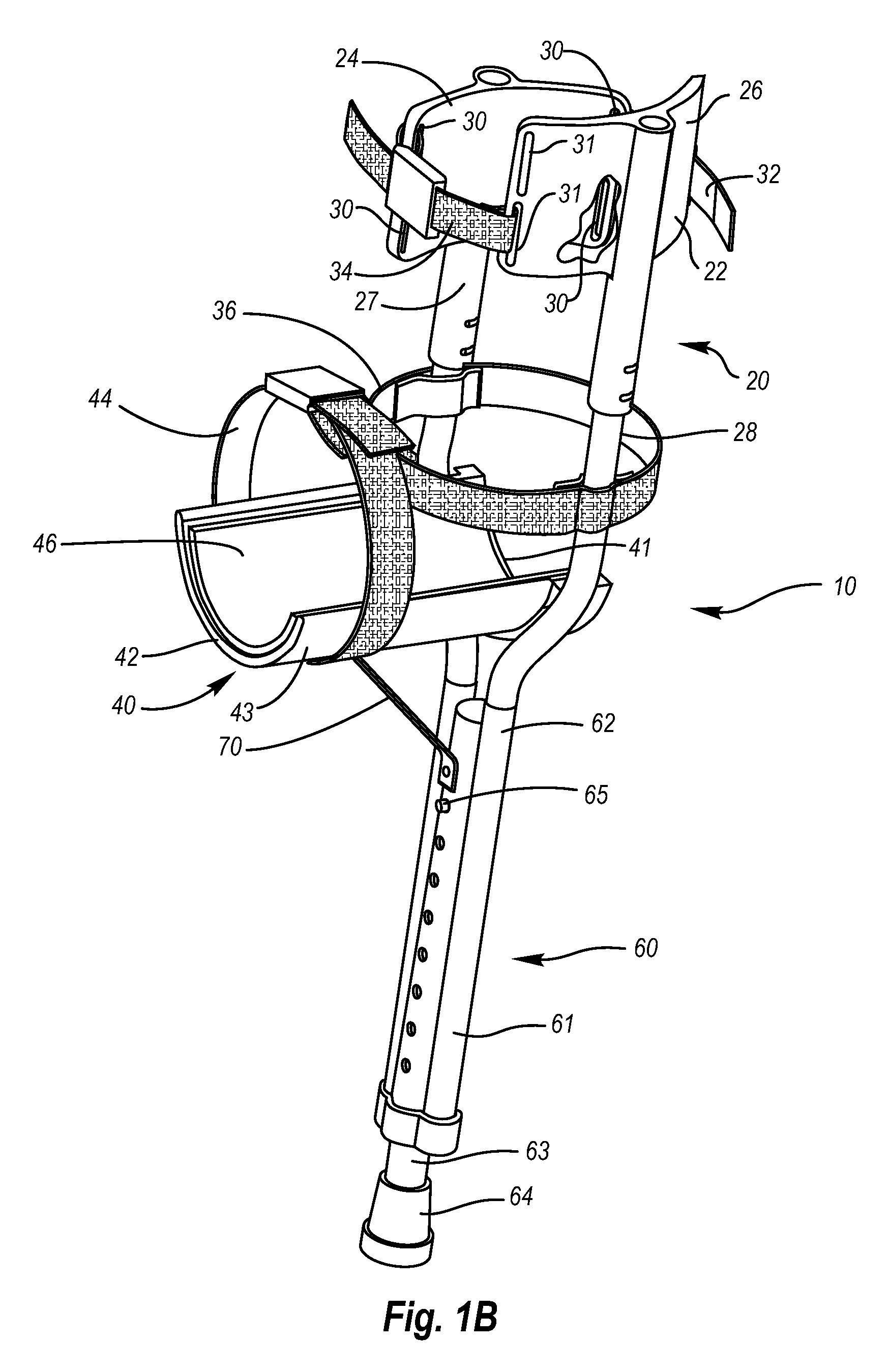
[0017]Referring initially to FIGS. 1A and 1B, shown are perspective views of the present invention. The views showing the device configured for use on a user's left leg (FIG. 1A) and configured for use on a user's right leg (FIG. 1B). The mono-crutch 10 having an upper leg support 20, a lower leg support 40, and a ground contact member 60.

[0018]The upper leg support 20 comprising the portion of the present invention configured for attaching to the upper leg portion (thigh) of a user. It is preferred that the upper leg support 20 comprise a pair of thigh pad portions, namely an upper thigh pad portion 22 and a lower thigh pad portion 24. The preferred material for the thigh pad portions being plastic, however other materials would work. The upper thigh pad portion 22 is preferably configured for use on the outside part of a user's leg, and therefore could be referred to as an “outer thigh pad portion,” whereas, the lower thigh pad portion 24 is configured for use on the inside portio...

second embodiment

[0033]Referring now to FIGS. 2 and 3, shown is the invention. FIG. 2 showing a perspective view, FIG. 3 showing a perspective, environmental (as worn) view of the embodiment of FIG. 2. The views showing the device 110 configured for use on a user's left leg. The mono-crutch 110 having an upper leg support 120, a lower leg support 140, and a ground contact member 160.

[0034]The upper leg support 120 comprising the portion of the present invention configured for attaching to the upper leg portion (thigh) of a user. It is preferred that the upper leg support 120 comprise a pair of thigh pad portions, namely an upper thigh pad portion 122 and a lower thigh pad portion 124. The upper thigh pad portion 122 is preferably configured for use on the outside part of a user's leg, and therefore could be referred to as an “outer thigh pad portion,” whereas, the lower thigh pad portion 124 is configured for use on the inside portion of a user's leg and therefore could be referred to as the “inner ...


PUM


Abstract

A mono-crutch for assisting the ambulation of individuals having injured or otherwise debilitated lower extremities. The mono-crutch having upper leg support with inner and outer support pads, a lower leg support for cradling a wearer's lower leg, and a ground contact member. The inner and outer support pads are configured so as to be able to be swapped or raised / lowered relative to one another, thereby allowing both right legged and left legged configurations to be created using the same mono-crutch.

Description

FIELD OF THE INVENTION[0001]The invention relates generally to medical ambulatory aids and more particularly relates to a partial crutch that can be connected to a user's leg.BACKGROUND OF THE INVENTION[0002]Frequently, individuals will injure or otherwise experience a debilitation of their lower extremities. For instance, a user may sprain an ankle or break a bone in his / her foot. While some such injuries may allow an individual to wear a “walking cast,” more often than not the injured person is prescribed a pair of crutches or other such ambulatory device. These crutches allowing the injured person to be mobile and stay involved in daily life (work obligations, family, etc.) with out the need for a wheel chair. Additionally, such ambulatory devices are frequently used by below knee (BK) amputees who can't afford or are otherwise between prosthetics.[0003]Existing crutches for temporary and sometimes long term use are one of two types. The first type uses an underarm pad and handle...

Claims


Application Information

Patent Timeline
Patent Type & Authority Patents(United States)
IPC IPC(8): A61H3/02A63B25/00
CPCA61H3/02A61H2201/165A61H2003/005
Inventor WEST, PHILLIP B.
Owner MOBILITY SOLUTIONS
Learn More