
Network node emulator and method of node emulation

a network node and emulator technology, applied in the field of network node emulators, can solve the problems of inability to fully emulate regular network traffic, time and effort required, and relatively large time gaps between messages

Inactive Publication Date: 2009-09-29
HARRIS CORP
View PDF24 Cites 25 Cited by
  • Summary
  • Abstract
  • Description
  • Claims
  • Application Information

AI Technical Summary

Problems solved by technology

One of the most significant challenges that exists in designing a new network node, a new network protocol, a new node software, etc., is in testing.
The drawbacks of this are the time and effort required, relatively large time gaps between messages, and the inability to fully emulate regular network traffic.
An actual network environment may offer realistic message traffic loads, traffic types, and response times. However, it may not offer a tester the opportunity or ability to supplement the on-going message traffic and stretch the test environment beyond normal traffic levels and traffic types.
However, this is expensive and time-consuming.
No device currently exists to fully emulate the behavior of a network node and to fully emulate the composition of network traffic.
The prior art approaches are lacking in terms of automation, language specification, approximation of dynamic node behavior, and linkage to time scales.
The prior art approaches are also lacking in an ability to individually address or characterize different aspects and attributes of the TCP / IP protocol.
In addition, the prior art approaches do not have a central integration of TCP / IP functionality, are not independent of platform and operating systems, are not expandable to accommodate new protocols, and cannot specify data contents of generated transmit messages.
More importantly, the approaches of the prior art are inadequate because they are merely reactive or filter-based.
Fixed-time packet transmission and reception is inadequate to fully emulate interactive node behavior.
In addition, the prior art approaches require specialized or additional hardware, and may not accommodate insertion of a node or node emulator into a real world network.

Method used


Image

  • Network node emulator and method of node emulation
  • Network node emulator and method of node emulation
  • Network node emulator and method of node emulation

Examples


example

[0102]Below is an example of an emulation script according to the invention. The example is purely illustrative, and is not exhaustive of the potential types and uses of the commands and modifiers.

[0103]

SAMPLE SCENARIO FILEstart 14:30:00event for 151.190.12.137triggertime 5000repeat 10 period 2, 4, 6, 1actionmsg size 256send to 151.190.9.11  151.190.9.21port 6768event for 151.190.10.100triggerrcv from 151.190.9.1match *repeat 4actionmsg “The quick brown fox jumped over the lazy dog!”send to 151.190.9.12  151.190.9.13  151.190.49.1event for 172.24.254.2triggertime 50repeat 10 period 5actiontos 2 prec 8 unicast port 4500 ttl 3msg “Hello World”send to 172.24.254.50port 5634   # destination port numberevent for 172.24.254.2listen DAT mcast 2300 225.10.10.10event for 151.190.13.10triggerrcv from 151.190.9.1match “{circumflex over ( )}hello world$” # will match on “hello world”repeat 3actionmsg [ protocol info ]send to 151.190.9.12  151.190.9.13  151.190.49.1event for 151.190.1.10triggerr...


PUM


Abstract

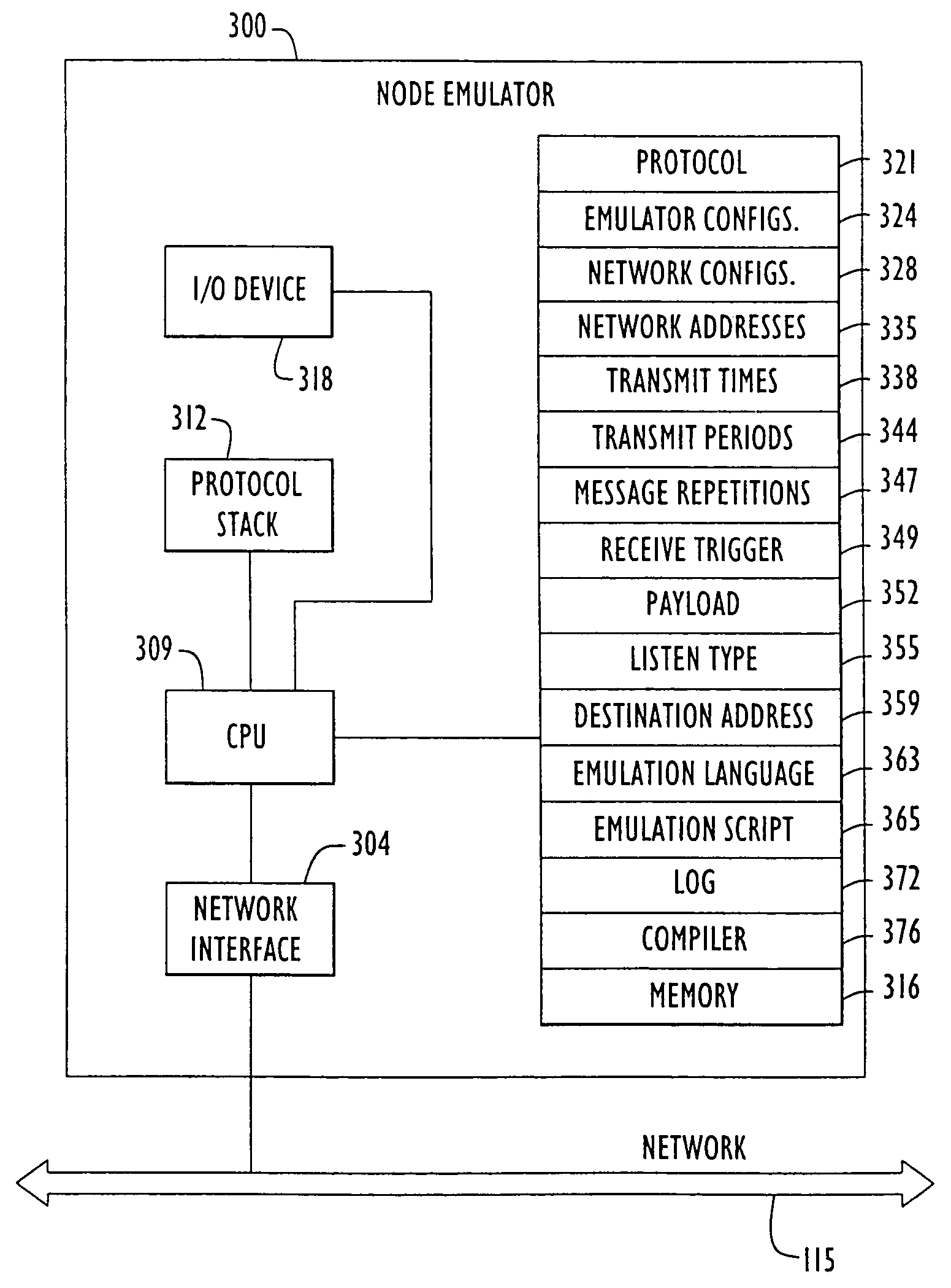
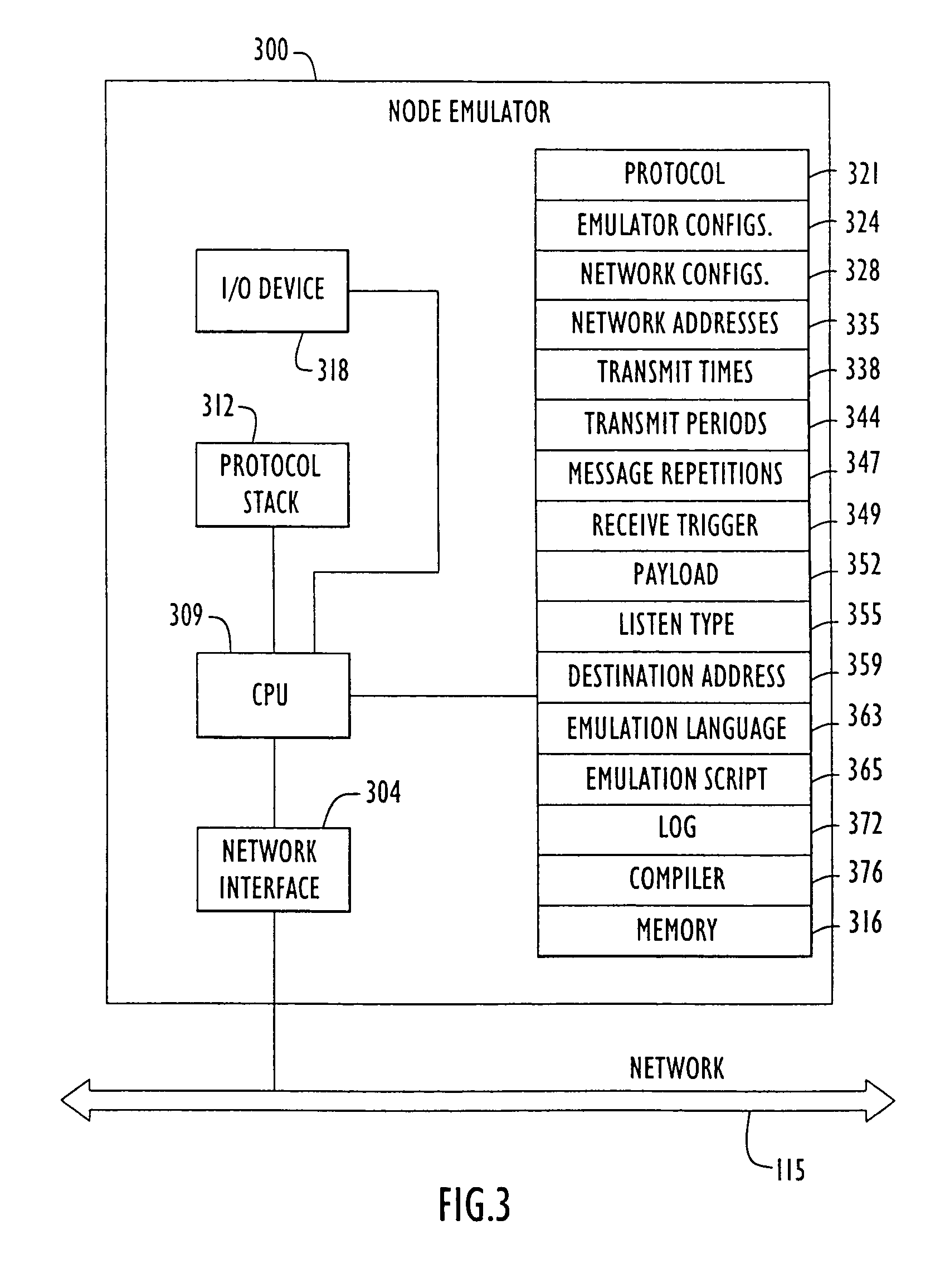
A method and apparatus is provided for network node emulation, including a node emulator, comprising a node interface, a memory, and a CPU. A method of generating an emulated network node includes the steps of generating an emulation script using a network node emulation language and operating a computer device according to the emulation script in order to transmit and receive data packets in the computer device. The method comprises receiving an incoming message, transmitting an outgoing message, and recognizing a response requirement in the incoming message. The method comprises responding to the incoming message by transmitting a response outgoing message if the incoming message includes a response requirement.

Description

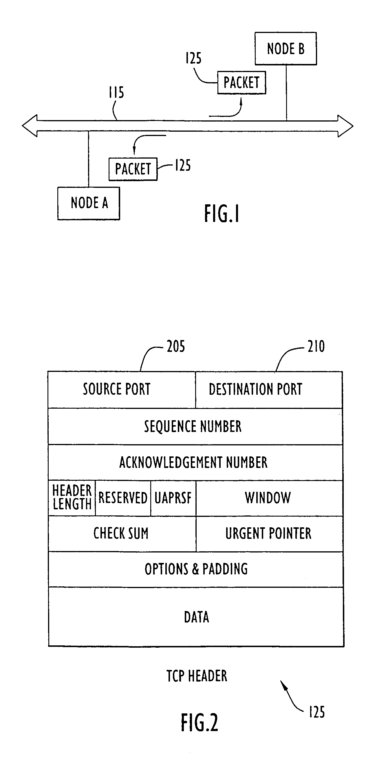
BACKGROUND OF THE INVENTION[0001]1. Field of the Invention[0002]The present invention relates generally to network node emulation, and more particularly to emulation of network node behavior.[0003]2. Description of the Background Art[0004]Computer networks have become widespread and ubiquitous. They are commonly used for data storage and manipulation, communications, commerce, information procurement, etc. By connecting together (networking) multiple computers or multiple computer networks, information may be easily shared, and shared in an almost instantaneous fashion.[0005]FIG. 1 shows a typical distributed electronic network 115 connecting two or more nodes, such as node A and node B as shown. The distributed electronic network 115 may be, for example, the Internet. A network node is a computer or computer device that is connected to the network and communicates over the network 115. A computer network may contain many such nodes, including computers, workstations, servers, route...

Claims


Application Information

Patent Timeline
IPC IPC(8): G06F9/455G06F15/173H04L12/24H04L29/06
CPCH04L43/50H04L67/38H04L69/22H04L67/131
Inventor PATEL, AMIT J.SALANT, NEIL K.
Owner HARRIS CORP
Learn More