
Method for tensioning side portions of shirt and body tensioning device applied for the method

a technology of side portions and body tensioning, applied in the field of method for tensioning the side portions of shirt, can solve the problems of reducing the working efficiency, and achieve the effects of low cost, low capability, and fast and neat finishing

Active Publication Date: 2009-09-29
SANKOSHA ENGINEERING CO LTD
View PDF6 Cites 5 Cited by
  • Summary
  • Abstract
  • Description
  • Claims
  • Application Information

AI Technical Summary

Benefits of technology

"This invention provides a method and device for applying tension to the side portions of a shirt. The method involves using a dummy with the shirt installed and extending the side pressing members of the shirt to apply tension. The device includes a controller to control the driving device for extending the side pressing members. The invention eliminates the need for an operator to determine the size of the shirt and measure the tension applying distance of the side pressing members, making the process easier, positive, and neat. The driving device can be an air cylinder or a motor, and the device can be installed at a lower inside part of the dummy to prevent leakage of hot air and steam. The invention also allows for easy synchronization of the side pressing members and reduces parts and manufacturing costs. The driving device can be an air cylinder or a pair of air cylinders installed at a high position to finish the shirt quickly and neatly without interfering with hot air and steam supply."

Problems solved by technology

Accordingly, this type of prior art device has been operated in compliance with a sensitive feeling of the operator, so that the operator has happened to mistake the size of the shirts and it has been frequently found that a manual correction of the shirt with an iron after mechanical finishing has been carried out.
In addition, since it was necessary for the operator to judge the size of the shirts in order to depress the switch corresponding to each of the sizes, it could not be avoided that a working efficiency was decreased.

Method used


Image

  • Method for tensioning side portions of shirt and body tensioning device applied for the method
  • Method for tensioning side portions of shirt and body tensioning device applied for the method
  • Method for tensioning side portions of shirt and body tensioning device applied for the method

Examples


Embodiment Construction

[0029]Referring now to the accompanying drawings, some preferred embodiments of the present invention will be described as follows.

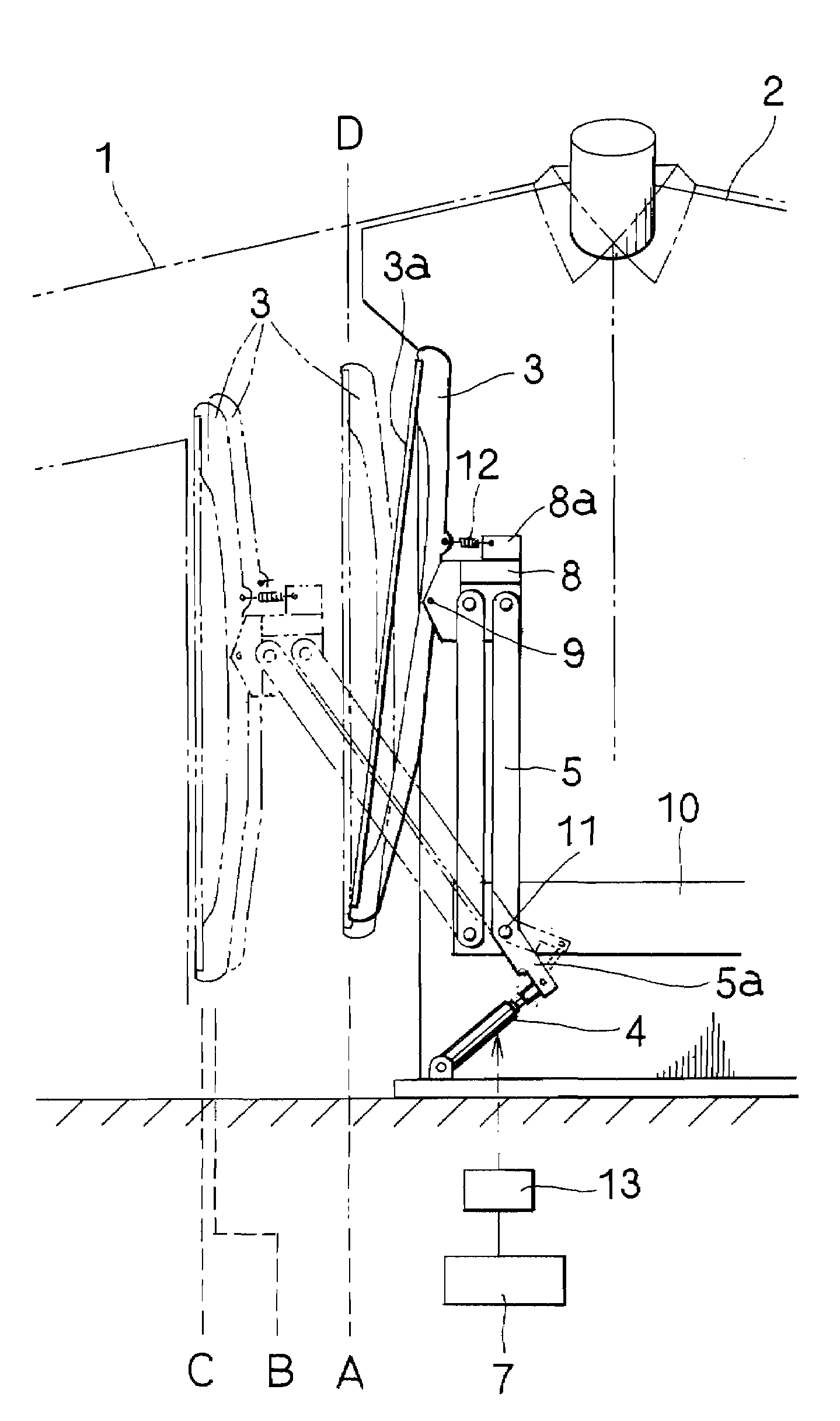
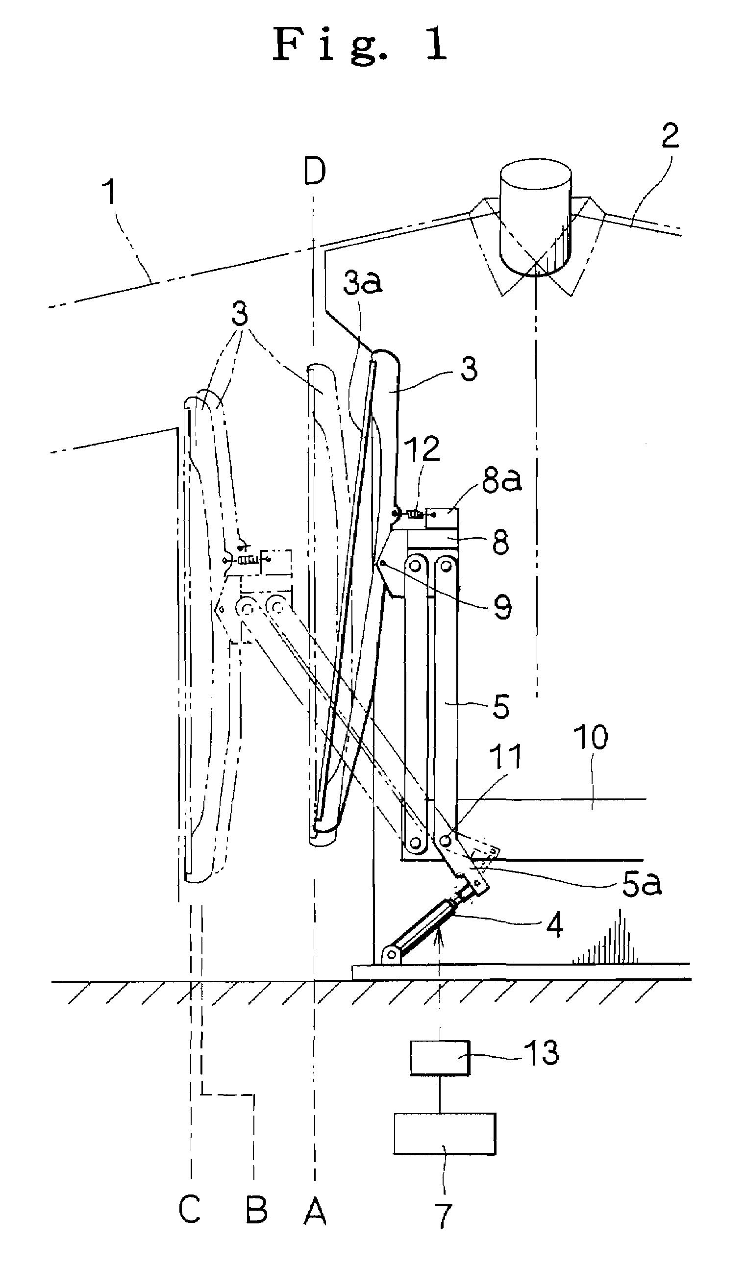
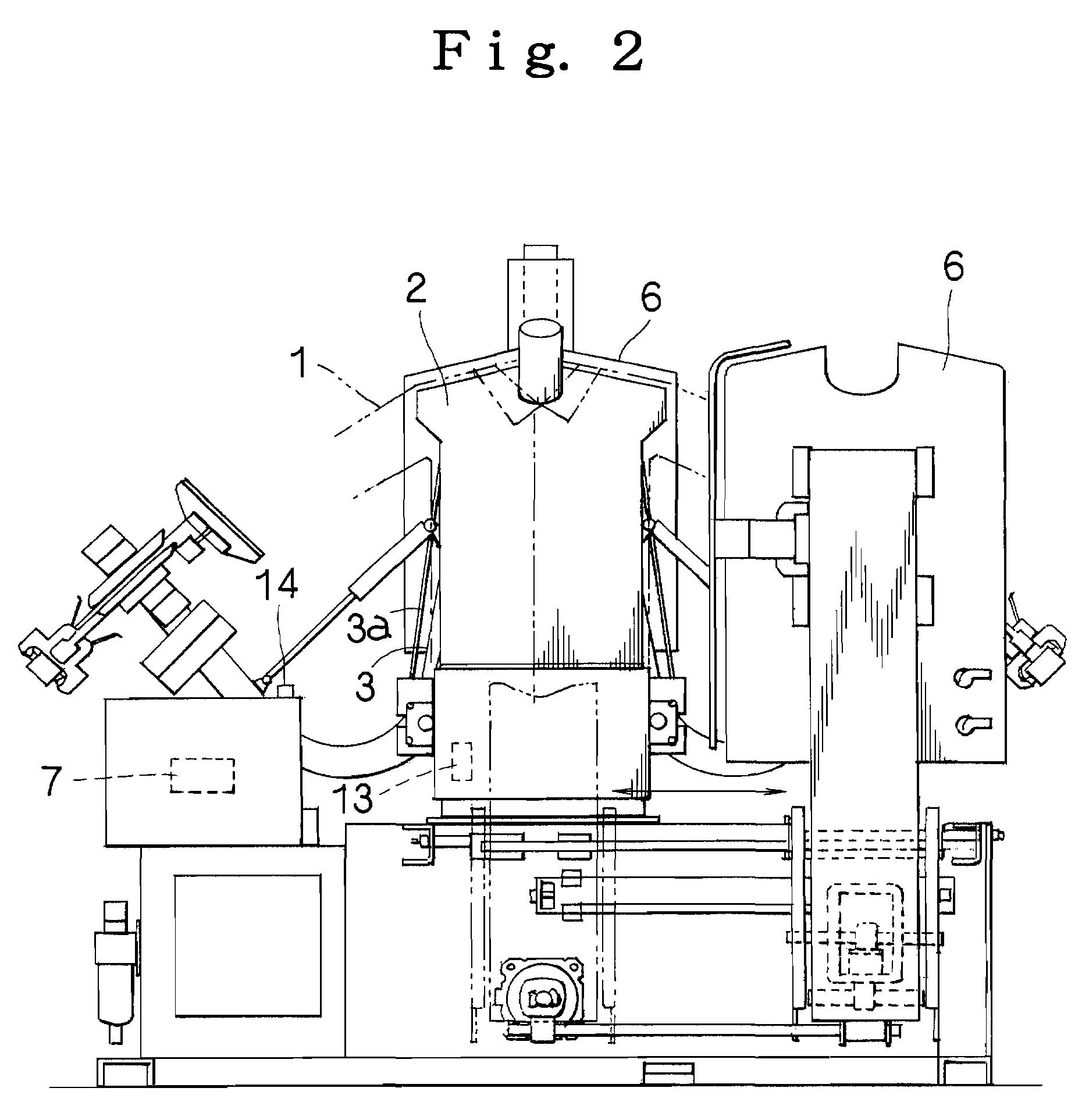
[0030]In FIG. 1 and the like, reference numeral 1 denotes a shirt such as a white shirt. Reference numeral 2 denotes a dummy on which this shirt 1 is put. Reference numeral 3 denotes side pressing members arranged vertically at both sides of the dummy 2. In addition, reference numeral 4 denotes a driving device for protruding the side pressing members 3 toward the side portions of the dummy 2.

[0031]A tension applying method of this invention finishes the side portions of a shirt 1 through a first tension applying process (a position B in FIG. 1) for extending side pressing members 3 up to the positions with the aforesaid driving device 4 where the side pressing members incline toward the side portions of a dummy 2 with their own weight (a position A in FIG. 1) and a second tension applying process.(a position C in FIG. 1) where the driving device 4 is dr...


PUM


Abstract

A shirt side tension applying method is provided for finishing side portions of a shirt. The method includes the step of providing a first tension applying process in which side pressing members at both portions of a dummy having the shirt put thereon are extended up to positions by a driving device after which the side portions of the shirt are tensioned with the side pressing members inclined by their own weight. The method also includes a second tensioning applying process in which, when the front and rear portions of the shirt are pressed, the same driving device operates again to cause the side pressing members to be further extended and the side portions of the shirt are finished in tension. The invention further contemplates a body tensioning device for finishing the side portions of the shirt according to the method described above.

Description

BACKGROUND OF INVENTION[0001]1. Field of Invention[0002]This invention relates to a method for tensioning the side portions of shirt. More particularly, this invention relates to a method for applying tension against the side portions of the shirt to make a neat press finishing state and a body tensioning device used for this method in a shirt press finishing machine for press finishing the shirt of a laundry item with a pair of front and rear press irons while the shirt is being put on the dummy.[0003]2. Description of Related Art[0004]As this type of prior art device, there is provided a device disclosed in the gazette of U.S. Pat. No. 6,868,996, for example. This prior art device is formed to have the side pressing members arranged vertically at both sides of the dummy and a driving device for protruding the side pressing members.[0005]It is further well known in the art that the size of shirts such as white shirts or the like is normally classified into large, middle and small s...

Claims


Application Information

Patent Timeline
Patent Type & Authority Patents(United States)
IPC IPC(8): D06F71/20D06F71/16
CPCD06F71/20
Inventor UCHIKOSHI, MITSUYUKI
Owner SANKOSHA ENGINEERING CO LTD
Learn More