Eureka AIR delivers breakthrough ideas for toughest innovation challenges, trusted by R&D personnel around the world.

Resonator

a resonance and waveguide technology, applied in the field of resonances, can solve the problems of low reproducibility of resonance frequency, poor mass productivity, large resonance size, etc., and achieve the effects of low loss, high mass productivity, and small siz

Inactive Publication Date: 2009-09-01
NTT DOCOMO INC
View PDF21 Cites 25 Cited by
  • Summary
  • Abstract
  • Description
  • Claims
  • Application Information

AI Technical Summary

Benefits of technology

[0010]The present invention has been made in view of the above described circumstances, and an object of the present invention is to provide a resonator capable of constituting a variable filter which has a small size, high mass productivity, low loss and high reproducibility of frequency.

Problems solved by technology

Therefore, there is a problem that the resonator becomes large.
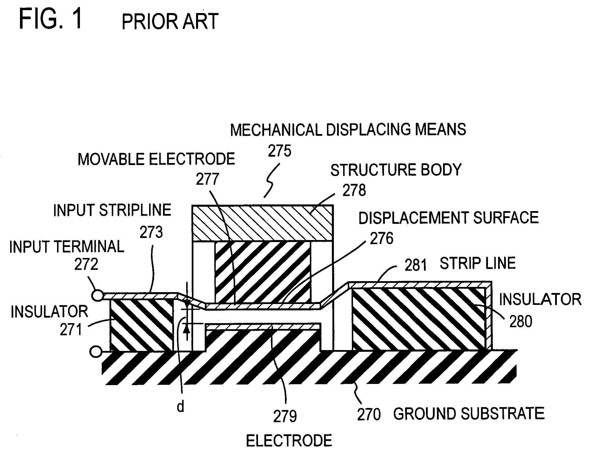
The conventional variable resonator of which resonance frequency can be changed, has also disadvantages that mass productivity is poor because the capacitive reactance component is changed by using the mechanical displacing means, and that reproducibility of the resonance frequency is low because the mechanical displacing means is liable to be affected by the ambient environment.
In the method, in addition to the size of the capacitor elements themselves, wirings for conducting signals are needed, as a result, the resonator becomes large.
Further, the resonator has a common disadvantage that the resonance frequency is changed due to the deviation in mounting the chip capacitors and thereby reproducibility of the resonance frequency is poor.

Method used


Image

  • Resonator
  • Resonator
  • Resonator

Examples


first embodiment

Embodiment 1

[0052]FIG. 2 shows a resonator of the present invention using a microstrip line. An input / output line 3 is formed on the surface of a dielectric substrate 2, on which reverse side a ground plane 1 is formed. A high frequency signal is inputted from one end of the input / output line 3. A resonant line 4 having a length of about a quarter of the wavelength λ of the resonant frequency f is connected to nearly a center part of the input / output line 3, and formed on the dielectric substrate 2 in the direction perpendicular to the input / output line 3. The end of the resonant line 4 is electrically connected to the grounded ground plane 1. A counter electrode 6 facing a partial area of the resonant line 4 with an air gap 100 of a distance d in the direction perpendicular to the resonant line 4 is arranged. The counter electrode 6 is supported by a conductor column 5, and the conductor column 5 is connected to the ground plane 1 by a not shown Via hole (a conductor electrically c...

embodiment 2

[0062]FIG. 6 shows an embodiment of the present invention, in which a further miniaturization is effected by increasing and decreasing the width of the resonance line in the lengthwise direction of the resonance line, that is, by forming recessions and projections at the side edges of the resonance line. The parts corresponding to those explained with reference to FIG. 2 are denoted by the same reference numbers, and the explanation of these parts is omitted. The shape of a resonant line 7 is different from that in FIG. 2. A high frequency signal is inputted from one end of the input / output line 3. The resonance line 7 having a same width W1 as the input / output line 3 and a length L1 is arranged approximately from the middle part of the input / output line 3 in the direction perpendicular to the input / output line 3. Both sides of a part with a length T extended from a position at a distance of L1 from the input / output line 3, are provided with widened parts 7a, 7b in parallel with the...

embodiment 3

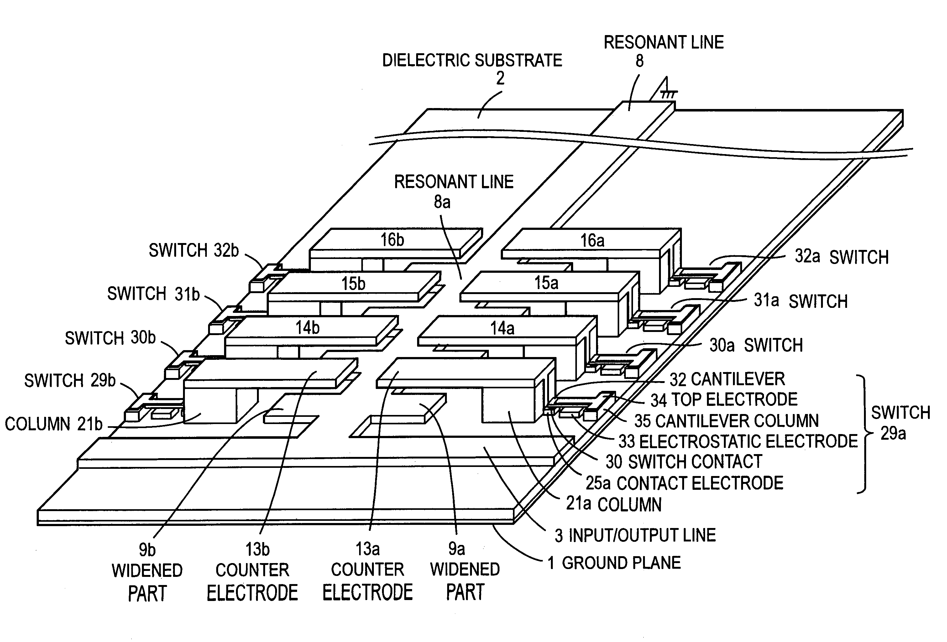
[0072]FIG. 8 shows an embodiment of a quarter wavelength line resonator with the tip short-circuited, in the case where the standing wave effect is taken into consideration. In the present embodiment, components already explained are denoted by the same reference numerals, and the explanation of the components is omitted. Widened parts 9a, 9b are arranged with a same pitch Lp at both side edges of a main resonant line 8 extended perpendicularly to the input / output line 3. For example, the pitch Lp is set to λ / 128, that is, the length of each of the widened parts 9a, 9b in the direction parallel to the input / output line 3 is set to λ / 128. In addition, the length of each of the widened parts 9a, 9b in the direction perpendicular to the input / output line 3 is also set to λ / 128. The widened parts 9a, 9b are repeatedly provided up to the position at a distance of λ / 8 from the input / output line 3. That is, four widened parts are arranged. The pitch Lp may not necessarily be the same, and ...


PUM


Abstract

An object of the present invention is to provide a resonator capable of constituting a variable filter which has a small size, high mass productivity, low loss and high reproducibility of frequency. According to the present invention, a resonator having a line structure formed on a dielectric substrate 2, is reduced in size by providing a counter electrode 6 in the direction perpendicular to a surface of a resonant line 4 for forming a capacitive reactance which is added to the resonance circuit. The resonator can be further reduced in size by providing widened parts 7a, 7b on the resonant line with the use of the skin effect of an electric signal propagating in the resonant line, so as to enable a large capacitive reactance to be obtained, and by providing the widened parts and the counter electrodes for a part on the resonant line where a magnitude of voltage standing wave is high.

Description

BACKGROUND OF THE INVENTION[0001]1. Field of the Invention[0002]The present invention relates to a resonator mounted in a radio communication apparatus, which comprises a dielectric substrate and a line of a predetermined length that is formed on the dielectric substrate.[0003]2. Description of the Related Art[0004]In the field of radio communication using high frequency, a necessary signal and an unnecessary signal are classified by taking out a signal of specific frequency out of many signals. A circuit performing this function is generally referred to as a filter and is mounted in a number of radio communication apparatuses. A resonator constituting a filter and having a line structure needs a line length of a quarter of or a half of the wavelength of the resonance frequency. In such resonators, a center frequency and a bandwidth which are design parameters are mostly fixed. When a plurality of frequency bands are used in a radio communication apparatus using these resonators, th...

Claims


Application Information

Patent Timeline
Patent Type & Authority Patents(United States)
IPC IPC(8): H01P1/20
CPCH01P1/20381H01P7/082H01P1/2039
Inventor KAWAI, KUNIHIROOKAZAKI, HIROSHINARAHASHI, SHOICHI
Owner NTT DOCOMO INC
Why Eureka
Eureka Blog
Learn More