
Piezoelectric device and method for manufacturing thereof

a piezoelectric device and piezoelectric/electrostrictive technology, applied in piezoelectric/electrostrictive transducers, generators/motors, transducer types, etc., can solve the problems of insufficient air tightness of the package, large bonding allowance that is difficult to maintain in the package, and high vacuum, so as to achieve sufficient bonding strength and maintain the effect of tightness

Inactive Publication Date: 2009-08-25
SEIKO EPSON CORP
View PDF9 Cites 26 Cited by
  • Summary
  • Abstract
  • Description
  • Claims
  • Application Information

AI Technical Summary

Benefits of technology

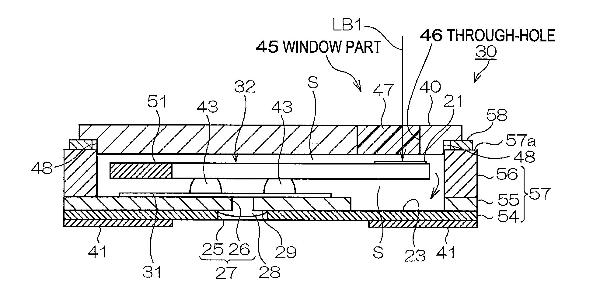
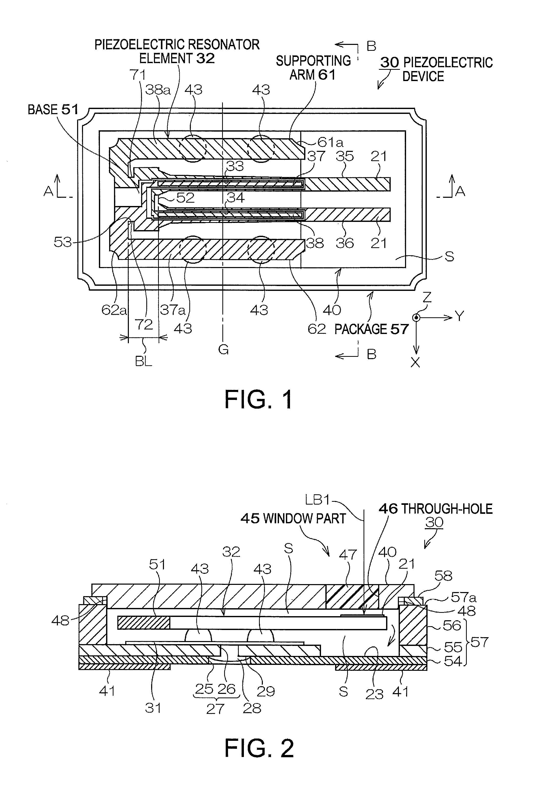
[0012]An advantage of the present invention is to provide a piezoelectric device and a method for manufacturing thereof in which the lid can be bonded without losing the air-tightness and the frequency can be adjusted accurately.
[0013]A piezoelectric device according to a first aspect of the invention, includes: a package; a piezoelectric resonator element housed in the package; a lid made of metal and bonded to the package by seam welding to seal the package air-tightly; a metal film for frequency adjustment that is provided to the piezoelectric resonator element; and a window part provided to the lid and enabling a light to transmit therethrough.
[0014]In this structure, even when the package is formed small in size and the bonding area with the lid is formed small accordingly, the lid is bonded by seam welding with the metal brazing material at the limited bonding area, providing sufficient bonding strength. The package can preferably maintain the air-tightness.
[0015]The lid for sealing the package is provided with the transparent window part. Therefore, if heating beam such as a laser light is transmitted to be introduced to the inside of the window part, the metal film for adjusting frequency that is formed on the piezoelectric resonator element can be partially transpired, thus being able to adjust the frequency by mass reduction.
[0016]Thus, according to the aspect of the present invention, such piezoelectric device can be provided that the lid can be bonded without losing the air-tightness and the frequency can be adjusted accurately.
[0017]In the piezoelectric device of the aspect, the lid may be a plate being long in one direction, and may be provided with the window part, that is formed by bonding a glass to a through-hole to be the window part, near one end part thereof in a length direction.

Problems solved by technology

However, the large bonding allowance is hard to be maintained in the package 2 that is miniaturized.
Therefore, if the low-melting glass is used as the brazing material, the bonding strength decreases, causing insufficient air-tightness of the package.
In addition, the inside of the package is degassed in the hole sealing process, providing high degree of vacuum.
In addition, the inside of the package is degassed in the sealing process, providing high degree of vacuum.

Method used


Image

  • Piezoelectric device and method for manufacturing thereof
  • Piezoelectric device and method for manufacturing thereof
  • Piezoelectric device and method for manufacturing thereof

Examples


second embodiment

[Piezoelectric Device ]

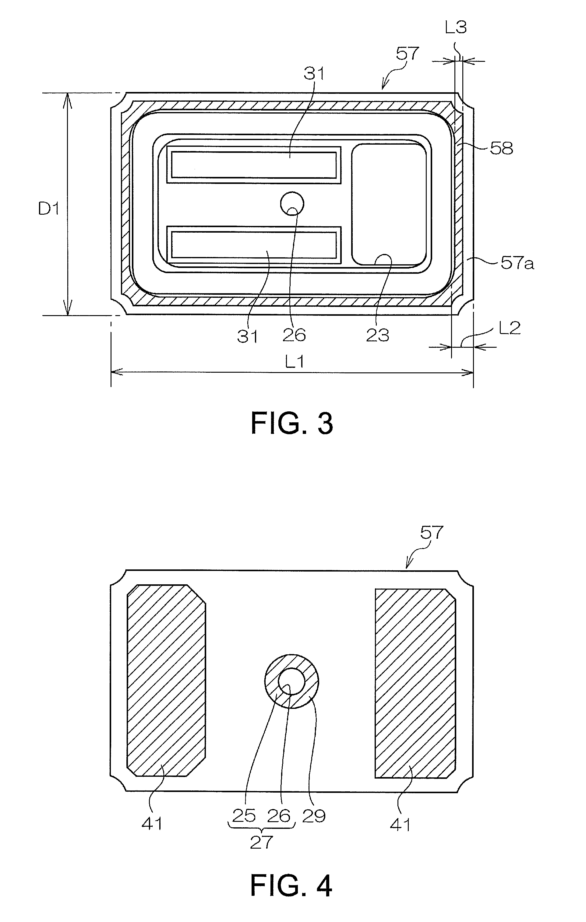
[0144]In the first embodiment, the lid 40 is provided with the window part 45 (FIG. 2) to which kovar glass (borosilicate glass) is to be provided. While, a structure according to a second embodiment does not have the window part 45 of the lid 40 as shown in FIG. 10. Other structures of the second embodiment are common to those of the first embodiment, and a schematic plan view thereof is shown in FIG. 1, a schematic plan view of the package is shown in FIG. 3, and a bottom plan view of the package is shown in FIG. 4.

[Method for Manufacturing Piezoelectric Device According to Second Embodiment]

[0145]As is the case with the first embodiment, the piezoelectric resonator element 32, the package 57, and the lid 40 are individually manufactured as a pre-process. After the pre-process is performed, the piezoelectric resonator element 32 that is completed will be bonded (ST1).

[0146]In particular, the conductive adhesives 43 are applied to the electrode parts 31 of FI...


PUM

PropertyMeasurementUnit
widthaaaaaaaaaa
sizeaaaaaaaaaa
sizeaaaaaaaaaa

Abstract

A piezoelectric device, includes: a package; a piezoelectric resonator element housed in the package; a lid made of metal and bonded to the package by seam welding to seal the package air-tightly; a metal film for frequency adjustment that is provided to the piezoelectric resonator element; and a window part provided to the lid and enabling a light to transmit therethrough.

Description

BACKGROUND[0001]1. Technical Field[0002]The present invention relates to a piezoelectric device in which a piezoelectric resonator element is housed in a package, and a method for manufacturing a piezoelectric device.[0003]2. Related Art[0004]Piezoelectric devices, including a piezoelectric resonator and a piezoelectric oscillator housing a piezoelectric resonator element in a package, have been widely used for small information equipment, such as hard disc drives (HDD), mobile computers and integrated circuit (IC) cards, for mobile communications equipment, such as cellular phones, car phones and paging systems, and for measuring instruments such as gyro sensors.[0005]Namely, such piezoelectric devices are known that a piezoelectric resonator element is housed in a package and then the package is sealed by a lid such as a glass plate.[0006]FIG. 13 shows such piezoelectric device 1 (see FIG. 1 of JP-A-2006-196932).[0007]Referring to the figure, the piezoelectric device 1 includes a ...

Claims


Application Information

Patent Timeline
Patent Type & Authority Patents(United States)
IPC IPC(8): H01L41/08H01L41/22
CPCH03H9/0595H03H9/1021Y10T29/42
Inventor KURODA, KATSUMI
Owner SEIKO EPSON CORP
Learn More