
Pneumatic tire

a pneumatic tire and tire body technology, applied in the field of pneumatic tires, can solve the problems of abnormal vibration, inability to employ the vulcanizing method utilizing the bladder inflation method, and thereby deterioration of the uniformity of the tire, so as to reduce abnormal vibration, reduce abnormal vibration, and reduce the effect of eccentric fitting amount relative to the rim

Inactive Publication Date: 2009-08-18
THE YOKOHAMA RUBBER CO LTD
View PDF12 Cites 0 Cited by
  • Summary
  • Abstract
  • Description
  • Claims
  • Application Information

AI Technical Summary

Benefits of technology

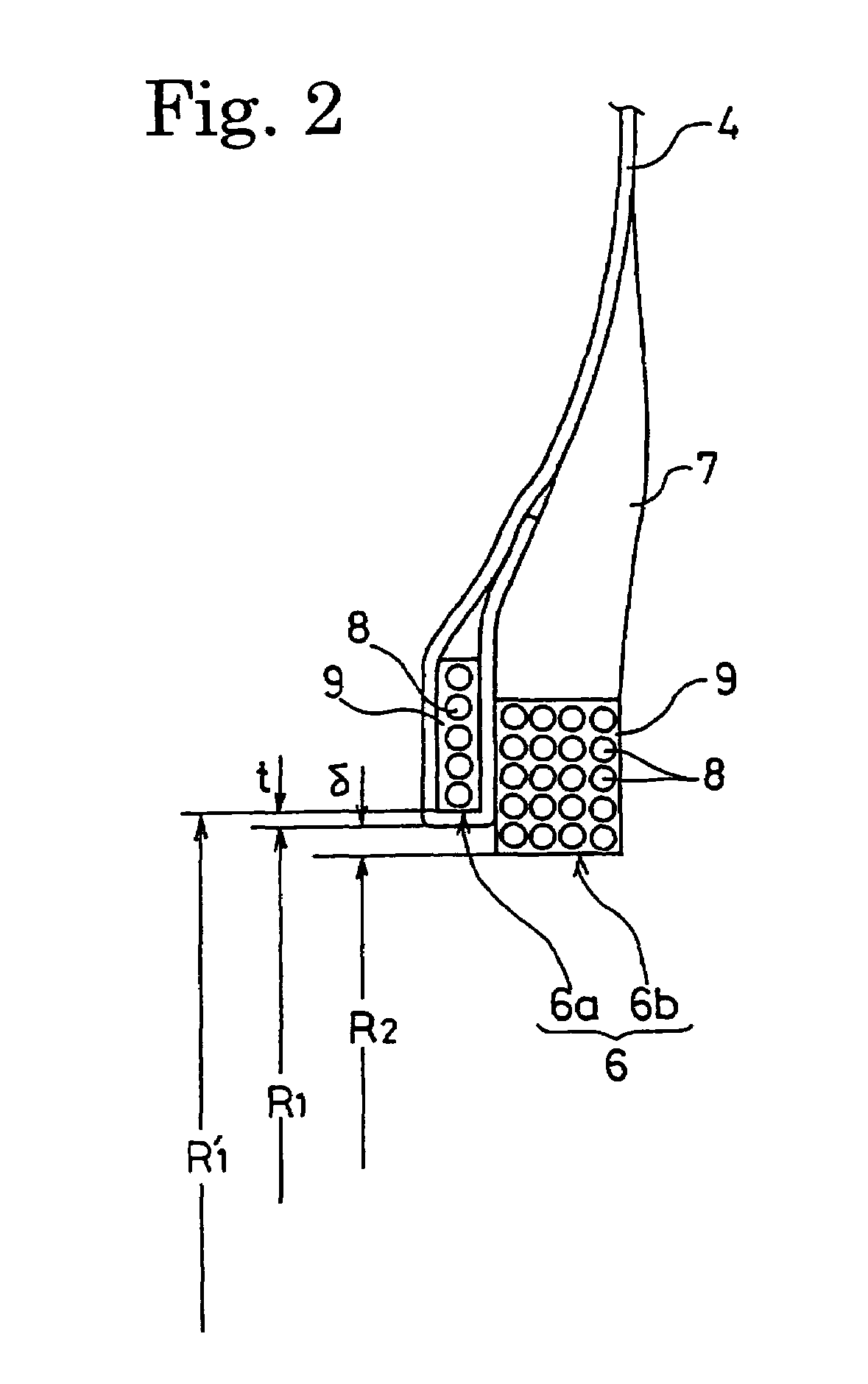
The present invention provides a pneumatic tire that reduces eccentric fitting with the rim without increasing cost. This is achieved by using a fastening bead core and a non-fastening bead core, where the non-fastening bead core has a smaller inner circumferential radius than the end of the carcass layer to be turned up. This reduces abnormal vibration when the vehicle is running and allows for the use of a bladder inflation type of vulcanizer for manufacturing the tire without increasing cost.

Problems solved by technology

Such bumps would increase a primary eccentric fitting component when the tire is mounted on a rim, and may sometimes cause abnormal vibration when a vehicle is running.
However, when an unvulcanized tire simply configured to interpose the end of the carcass layer between the split portions of the bead core is subjected to vulcanization with a bladder inflation type vulcanizer, the end of the carcass layer may sometimes be pulled out of the bead core when the unvulcanized tire is pushed upward by the bladder.
For this reason, it is not possible to employ the vulcanizing method utilizing the bladder inflation for vulcanizing this pneumatic tire.
Otherwise, widths of ends of the carcass cords to be interposed between the split portions of the bead core may become uneven after thermal contraction of the cords, and uniformity of the tire is thereby deteriorated.
Accordingly, this method requires tremendous operations for managing the tension of the carcass cords.
As a result, overall operability is substantially reduced and manufacturing costs are increased.

Method used


Image

  • Pneumatic tire
  • Pneumatic tire
  • Pneumatic tire

Examples


examples

[0033]Two types of pneumatic radial tires (Examples 1 and 2) were fabricated by setting the tire size as 205 / 65R15 and applying the tire structure as shown in FIG. 1 while providing one carcass layer in common. Meanwhile, the thickness t of the carcass layer, the difference (t+δ) between the inner circumferential radius R1′ of the fastening bead core and the inner circumferential radius R2 of the non-fastening bead core, and the difference δ between the inner circumferential radius R1 of the end of the carcass layer to be turned up around the fastening bead core and the inner circumferential radius R2 of the non-fastening bead core (a radial difference after turning up) are changed between these tires as shown in Table 1.

[0034]On the other hand, a radial tire having a conventional structure (Conventional Example) was fabricated by applying the same tire size as above. However, this tire was different from the above-mentioned tires in that the two types of the bead cores in the tire ...


PUM


Abstract

In a pneumatic tire composed of a carcass layer crossing between a pair of left and right bead cores, the bead cores comprise a fastening bead core for fastening an end of the carcass layer to be turned up around the fastening bead core, and a non-fastening bead core free from the end of the carcass layer. An inner circumferential radius R2 of the non-fastening bead core is set smaller than an inner circumferential radius R1 of the end of the carcass layer to be turned up around the fastening bead core.

Description

BACKGROUND OF THE INVENTION[0001]1. Field of the Invention[0002]The present invention relates to a pneumatic tire and, more specifically, to a pneumatic tire capable of drastically reducing an eccentric fitting amount relative to a rim.[0003]2. Description of the Related Art[0004]Generally, a carcass layer of a pneumatic tire is configured to be fastened by folding both ends respectively around a pair of left and right bead cores. In this way, by fastening the carcass layer by folding the both ends thereof around the bead cores, it is possible to avoid the ends of the carcass layer from being pulled out of the bead cores when an unvulcanized tire is pressed against an inner surface of a mold from inside by inflating a bladder during vulcanization forming, and to provide carcass cords with uniform tension in order to improve uniformity of the tire.[0005]However, the carcass layer is formed by winding a belt-shaped carcass material in a circumferential direction of the tire and then b...

Claims


Application Information

Patent Timeline
Patent Type & Authority Patents(United States)
IPC IPC(8): B60C15/00B60C15/04B60C15/05B60C1/00B60C15/06
CPCB60C15/0081B60C15/05Y10T152/10819Y10T152/10846
Inventor IIDA, EIICHI
Owner THE YOKOHAMA RUBBER CO LTD
Learn More