Eureka AIR delivers breakthrough ideas for toughest innovation challenges, trusted by R&D personnel around the world.

Ultrasonic oil/water tank level monitor having wireless transmission means

a technology of ultrasonic transducer and oil/water tank, which is applied in the direction of liquid/fluent solid measurement, machines/engines, instruments, etc., can solve the problems of incomplete monitoring procedure, high cost, environmental and/or safety hazards, etc., and achieve the effect of improving the accuracy of data

Active Publication Date: 2009-07-21
OLEUMTECH CORP
View PDF9 Cites 18 Cited by
  • Summary
  • Abstract
  • Description
  • Claims
  • Application Information

AI Technical Summary

Benefits of technology

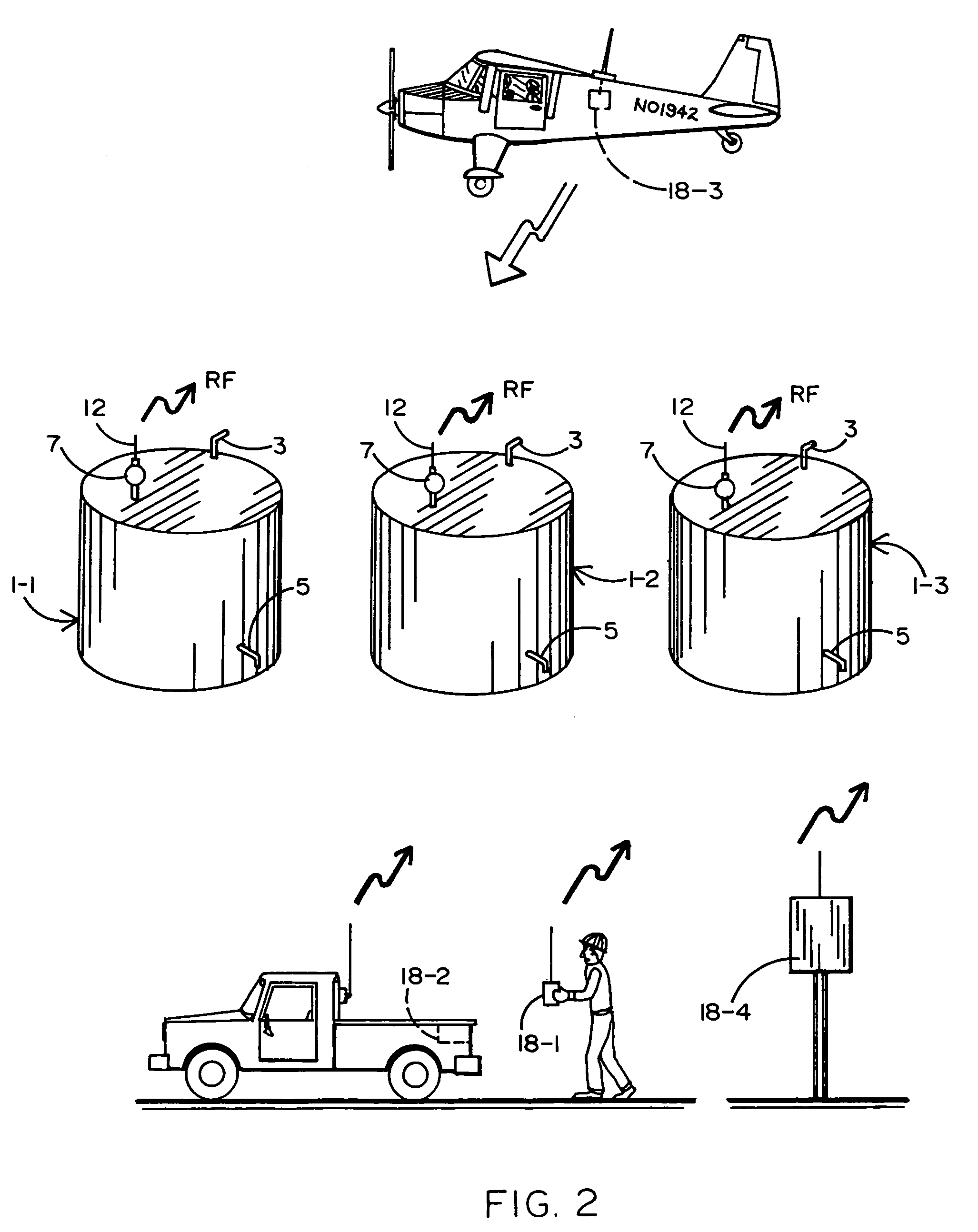
[0008]A wireless fluid level monitor is disclosed having an ultrasonic transducer that is capable of providing an accurate indication of the level of oil or water that is stored in a recovery tank of the kind that is typically located within an explosive environment near an oil or gas well. The fluid level monitor is coupled to an existing fitting at the top of the tank such that the ultrasonic transducer is received within the tank below the top, and the acoustic axis of the ultrasonic transducer is directed vertically downward towards the fluid to be monitored. The fluid level monitor is surrounded and protected by a gas tight and explosion proof rated casing. An RF transceiver having an antenna is capable of sending data to a mobile or stationary data collector or relay that is located outside the explosive environment by which to indicate the level of oil / water in the tank, the rate at which the tank is being filled, and the volume (in barrels) of oil / water in the tank, so that the efficiency of the well associated with the tank can be determined.
[0012]In order to permit the oil level readings to be calibrated for accuracy, a reference rod is affixed to the protective housing in which the ultrasonic transmitter is encased, so that the reference rod extends downwardly from the top of the tank towards the surface of the oil to be monitored. The reference rod carries one or more (e.g., stainless steel) acoustic reflectors that are attached (e.g., pinned) at predetermined fixed (e.g., four foot) intervals therealong. Each reflector lies within the ultrasonic beam and is adapted to reflect an echo pulse back to the ultrasonic transducer. Depending upon the time of flight between the incident pulse and the echo pulse, the main CPU of the fluid level monitor calculates the distance of the reflector from the ultrasonic transmitter and compares this distance with the known fixed distance. The main CPU will then make corresponding compensations to the time of flight between the incident pulse and the return pulse that is reflected off the surface of the oil back to the transducer to account for the environment (e.g., temperature, pressure and hydrocarbon vapors) within the tank, whereby to improve the accuracy of the data that is transmitted by the fluid level monitor at its antenna.

Problems solved by technology

Accurate monitoring is required to reduce the risks of an overflow condition and potential oil spillage at the tank site which could result in an environmental and / or safety hazard.
The aforementioned technique of having to visit the tanks in the field on a one-by-one basis at which to use a string test line and make a manual record of the oil levels is very time consuming, expensive and not completely accurate.
Moreover, the monitoring procedure is completed at relatively long intervals, such that a tank approaching full capacity may not be detected in time to avoid an overflow.
However, such ultrasonic methods tend to be inaccurate because they fail to take into account the environment within the tank in which the level measurements are to be taken.
For example, temperature and pressure changes within the tank, surface ripples, a short measurement range to the surface of the oil, and hydrocarbon vapors which fill the tank above the oil may all give rise to false readings and an indication of more or less oil than is actually present.
In addition, conventional ultrasonic monitoring methods are typically limited to tanks which are no greater than twelve feet high.
In this regard, the level data is often transmitted over wire lines which mandates an independent source of power, increases the cost of installation and maintenance, and limits the rate and range at which data can be transmitted.
Furthermore, a costly vapor tight conduit running above the tank is also required to surround and protect those wires which transmit the oil level data.
The environment in which the tank level measurements are taken is known to be very hostile and corrosive.
More particularly, the environment inside and surrounding an oil storage tank is typically acidic, includes a high concentration of potentially volatile vapors, and is subject to temperature extremes which often range from as low as −30 degrees C. to as high as +60 degrees C. Workmen who must enter the hazardous environment of an oil well and its neighboring storage tank to collect or receive oil level data are exposed to personal risk.

Method used


Image

  • Ultrasonic oil/water tank level monitor having wireless transmission means
  • Ultrasonic oil/water tank level monitor having wireless transmission means
  • Ultrasonic oil/water tank level monitor having wireless transmission means

Examples


Embodiment Construction

[0022]FIG. 1 of the drawings shows a conventional oil storage tank 1 that is located in the field in the vicinity of an oil well. While reference will be made herein to an oil storage tank, it is to be expressly understood that other fluids, such as water, may also be stored within tank 1. The oil tank 1 is filled via an inlet 3 with oil that is pumped from the adjacent oil well. Oil is removed from the tank 1 when full via an outlet 5 to be transported by truck to a refinery for processing. The tank 1 would be typically located adjacent a gas well had water been stored therein instead of oil.

[0023]In accordance with the present invention, a wireless fluid level monitor 7 is mounted on top of the tank 1 to be responsive to the level of oil with which the tank is filled or partially filled. As will be explained in greater detail hereinafter, the fluid level monitor 7 includes an ultrasonic transducer having a vertical acoustic axis that is directed downwardly from above the oil to be...


PUM


Abstract

An ultrasonic monitor to measure the level of a fluid (e.g., oil or water) within a storage tank. The ultrasonic monitor is surrounded by a gas-tight, explosion-proof casing that is coupled to the top of the tank so that the acoustic axis of a (e.g., 59 KHz) ultrasonic transducer is directed downwardly towards the surface of the fluid. The ultrasonic transducer is encased within a protective (e.g., Delrin) housing so as to resist the hostile (e.g., acidic, gaseous vapors and extreme temperature) conditions within the tank. A main CPU is interconnected between the ultrasonic transducer and an RF transceiver having an antenna from which fluid level data calculated by the main CPU can be transmitted over a wireless communication path. A reference rod having at least one acoustic reflector located at a known distance therealong extends downwardly from the housing of the ultrasonic transducer towards the surface of the fluid. The main CPU is responsive to the time of flight between incident signals generated by the acoustic transducer and return and echo signals reflected off the surface of the fluid and the acoustic reflector for calculating the corresponding distance between the fluid and the transducer. The main CPU is adapted to adjust the time of flight to compensate for errors introduced by the environment (e.g, gas vapors, pressure, etc.) of the tank depending upon the echo signal that is reflected to the acoustic transducer by the reflector of the reference rod.

Description

BACKGROUND OF THE INVENTION[0001]1. Field of the Invention[0002]This invention relates to a fluid level monitor having an ultrasonic transducer that is adapted to accurately detect the level of oil or water in a storage tank of the kind that is typically located in the field near an oil or gas well. The monitor includes an explosion proof casing and wireless transmission means by which fluid level data is sent to a remote mobile or stationary data collector or relay.[0003]2. Background Art[0004]It is desirable to be able to monitor the level of oil (or water) that is removed from an oil (or gas) well and stored within a recovery tank near the well. Accurate monitoring is required to reduce the risks of an overflow condition and potential oil spillage at the tank site which could result in an environmental and / or safety hazard. One conventional technique to accomplish such oil level monitoring is for a workman to go out in the field and drive from tank-to-tank. The workman climbs to ...

Claims


Application Information

Patent Timeline
Patent Type & Authority Patents(United States)
IPC IPC(8): G01F23/28
CPCG01F25/0061G01F23/2962G01F25/20
Inventor PETERS, GEORGE W.
Owner OLEUMTECH CORP
Why Eureka
Eureka Blog
Learn More