
Optical path switching device

a technology of optical path switching and failure protection, which is applied in the direction of multiplex communication, transmission monitoring, instruments, etc., can solve the problems of large size, increased size, and high cost of conventional failure protection optical path switch devices

Inactive Publication Date: 2009-07-14
NABLESCO CORP
View PDF12 Cites 8 Cited by
  • Summary
  • Abstract
  • Description
  • Claims
  • Application Information

AI Technical Summary

Problems solved by technology

Thus, the failure in the optical communication network is recovered.
However, a conventional failure-protection optical path switch device has a disadvantage of being of large size and expensive.
Accordingly, the respective components are increased in size, and require materials and man-hours for packaging, thereby becoming expensive.
Accordingly, the components must be connected by means of fusion or adhesion between the fibers; however, since at least about 3 cm of work space is required to connect the fibers, the components cannot be disposed close to each other, whereby the device becomes large.
Furthermore, since connection of optical fibers within a small space requires a high level of skill, such work is expensive.
However, since the optical fiber cannot be bent at sharp angles, storage of slack fiber for allowing the optical fiber a margin is required.
For the above reasons, the conventional failure-protection optical path switch device is of large size and expensive.

Method used


Image

  • Optical path switching device
  • Optical path switching device
  • Optical path switching device

Examples


Embodiment Construction

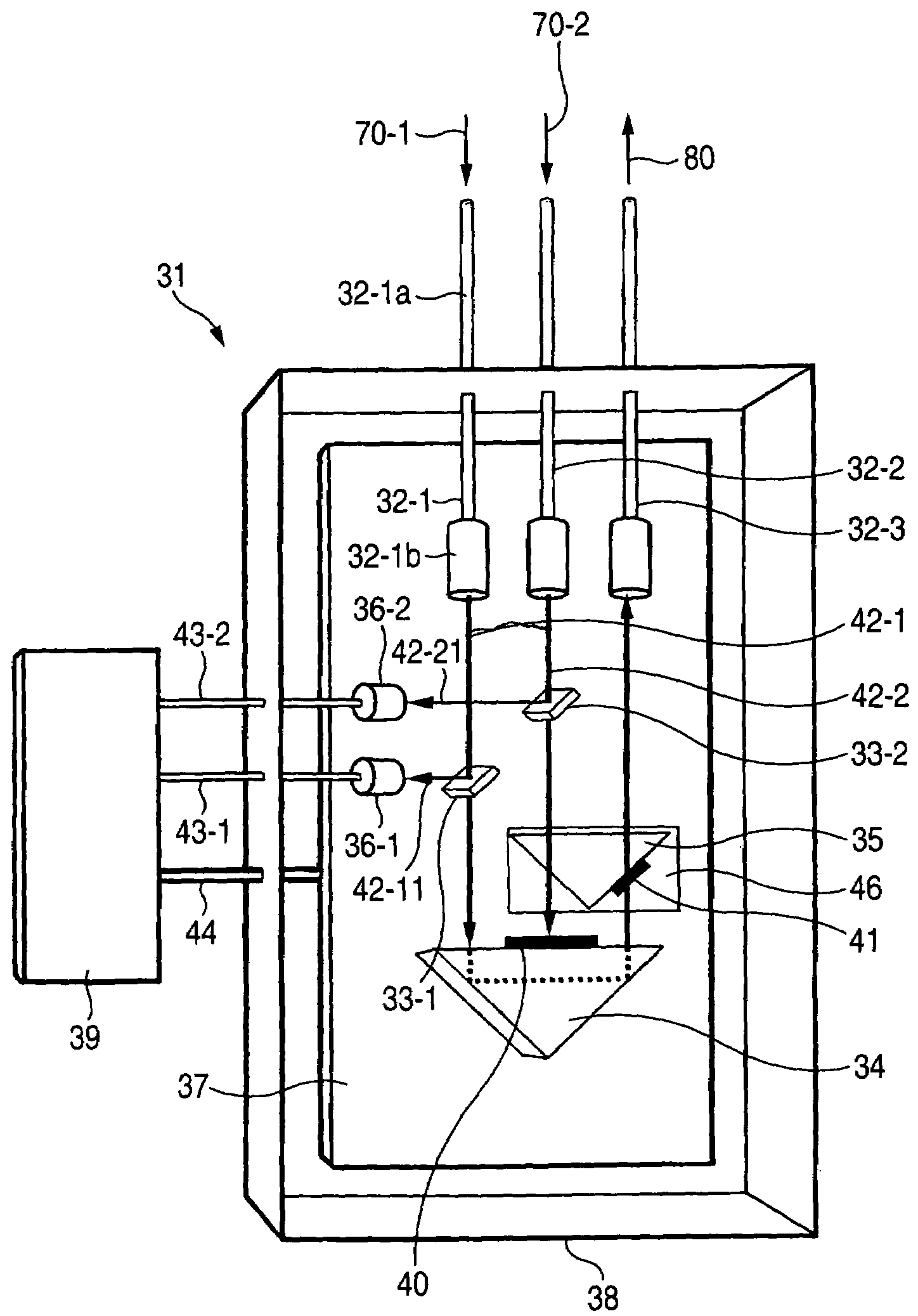
[0033]FIGS. 4 to 7 are views for explaining a failure-protection optical path switching device according to the present invention.

[0034]FIG. 4 is a top view showing the configuration of the failure-protection optical path switching device.

[0035]A failure-protection optical path switching device 31 comprises optical fiber collimators 32-1 and 32-2 (input means), an optical fiber collimator 32-3 (output means), optical tap devices 33-1, 33-2, photodiodes 36-1, 36-2 (monitor means), a fixed prism 34 and a movable prism 35 (switching means), a platform 37, a package case 38, and electronics 39 (control means).

[0036]As shown in FIG. 4, the optical fiber collimators 32-1, 32-2, and 32-3 are arranged in parallel. Each of the optical fiber collimators is constituted of an optical fiber, and a lens attached on a tip of the optical fiber. For instance, the optical fiber collimator 32-1 is constituted of an optical fiber 32-1a and a lens 32-1b, and is designed and assembled so that parallel lu...


PUM


Abstract

An optical path switching device includes compact and unpackaged components; the components are mounted onto a single platform; and the components are coupled by luminous flux. Connection between optical fibers is negated. In particular the optical path switching device includes an optical input, an optical output, an optical branching device and an optical signal detection device. At least two of the optical input, the optical output, the optical branching device and the optical signal detective device are mounted onto a single platform.

Description

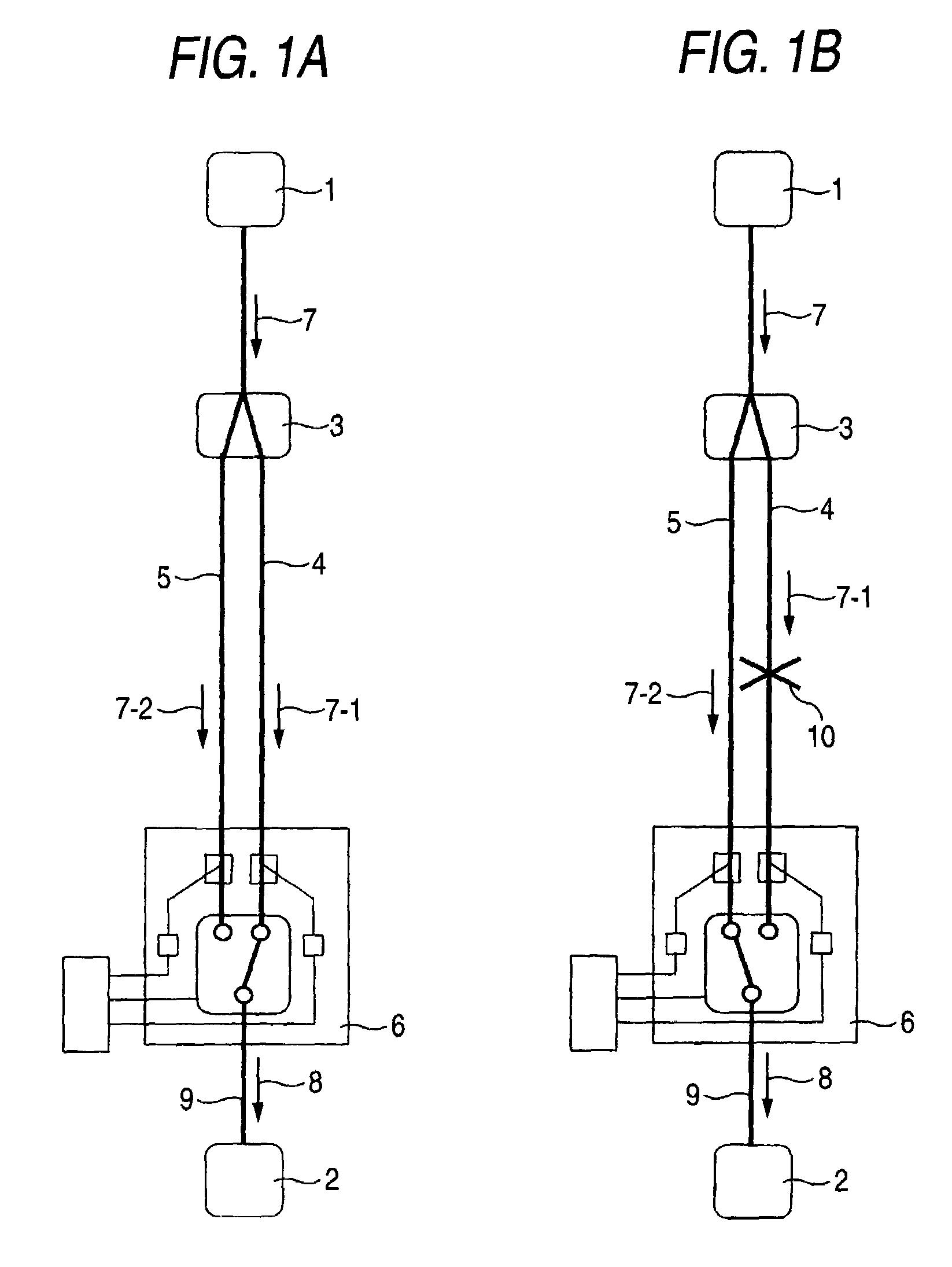
CROSS-REFERENCE TO RELATED APPLICATIONS[0001]This application is a continuation of International Application No. PCT / JP2004 / 013172, filed Sep. 9, 2004, the disclosure of which is incorporated herein by reference.BACKGROUND OF THE INVENTION[0002]The present invention relates to a failure-protection optical path switching device for switching between optical paths employed in the field of optical communication, such as an optical communication network or an optic LAN.[0003]In an optical communication network, when a failure occurs in a working line that is transmitting optical communication signals, the line is switched to a backup line, thereby preventing a communication failure.[0004]FIGS. 1A and 1B are views for explaining a 1+1 failure recovery system adopted in a point-to-point optical communication network. FIG. 1A is a view for explaining a case where no failure has occurred, and FIG. 1B is a view for explaining a case where a failure has occurred.[0005]The 1+1 failure recovery...

Claims


Application Information

Patent Timeline
Patent Type & Authority Patents(United States)
IPC IPC(8): H04J14/00G02B6/35H04B10/40
CPCG02B6/3582G02B6/3562G02B6/352G02B6/3586
Inventor TOGAWA, MASAYUKIKOBAYASHI, MORIO
Owner NABLESCO CORP
Learn More