Seat reclining mechanism

a seat and mechanism technology, applied in the direction of movable seats, vehicle components, vehicle arrangements, etc., can solve problems such as cost increas

Inactive Publication Date: 2009-06-30
DELTA KOGYO CO LTD
View PDF20 Cites 23 Cited by
  • Summary
  • Abstract
  • Description
  • Claims
  • Application Information

AI Technical Summary

Benefits of technology

[0009]In view of the above problem, it is an object of the ...

Problems solved by technology

In this case, plural types of internal gear members have to be prepar...

Method used


Image

  • Seat reclining mechanism
  • Seat reclining mechanism
  • Seat reclining mechanism

Examples


Embodiment Construction

[0034]With reference to the drawings, the present invention will now be specifically described based on a preferred embodiment thereof.

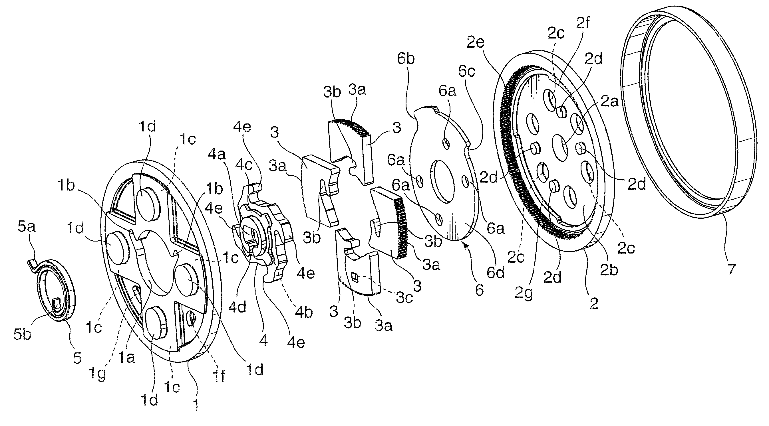
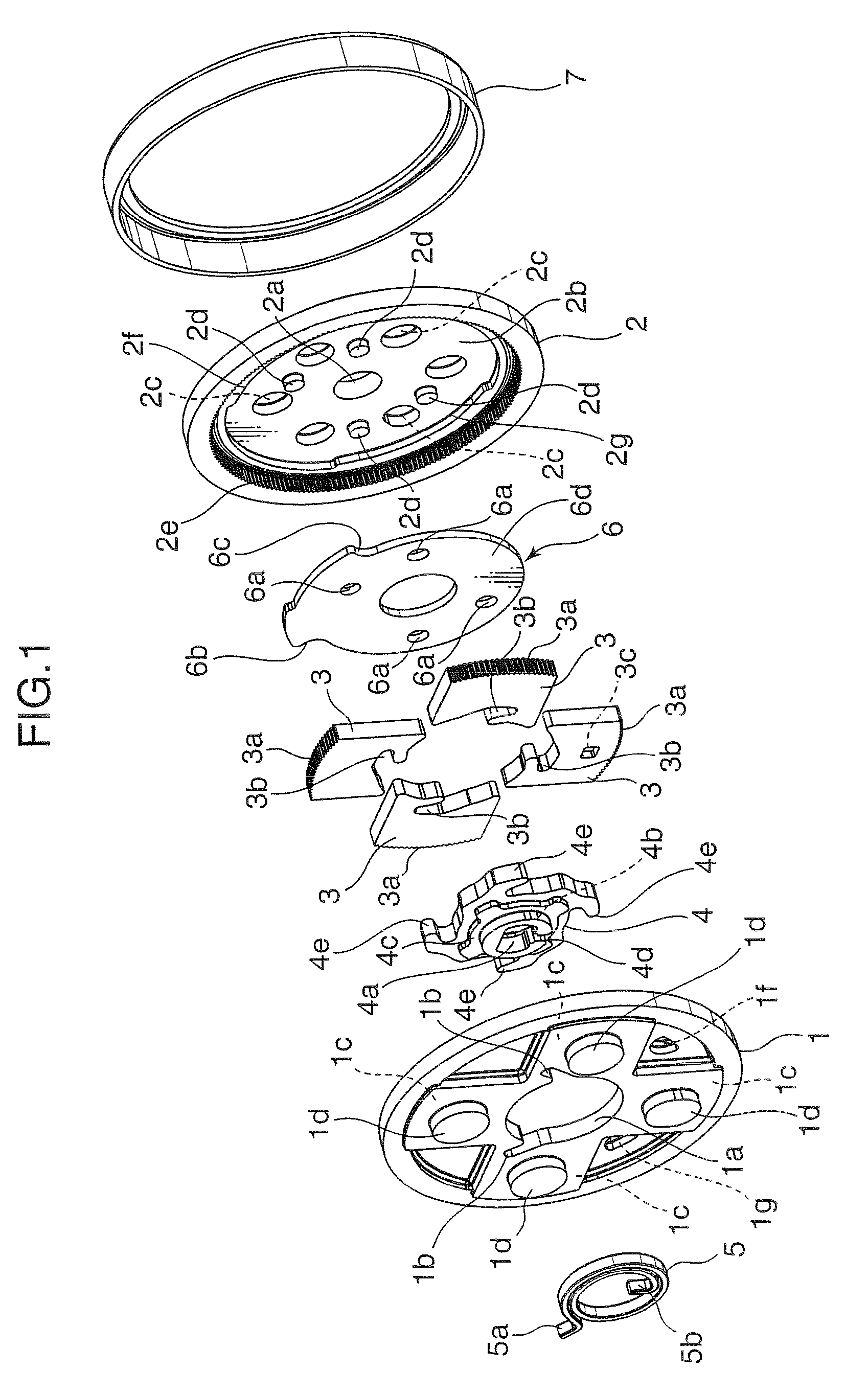
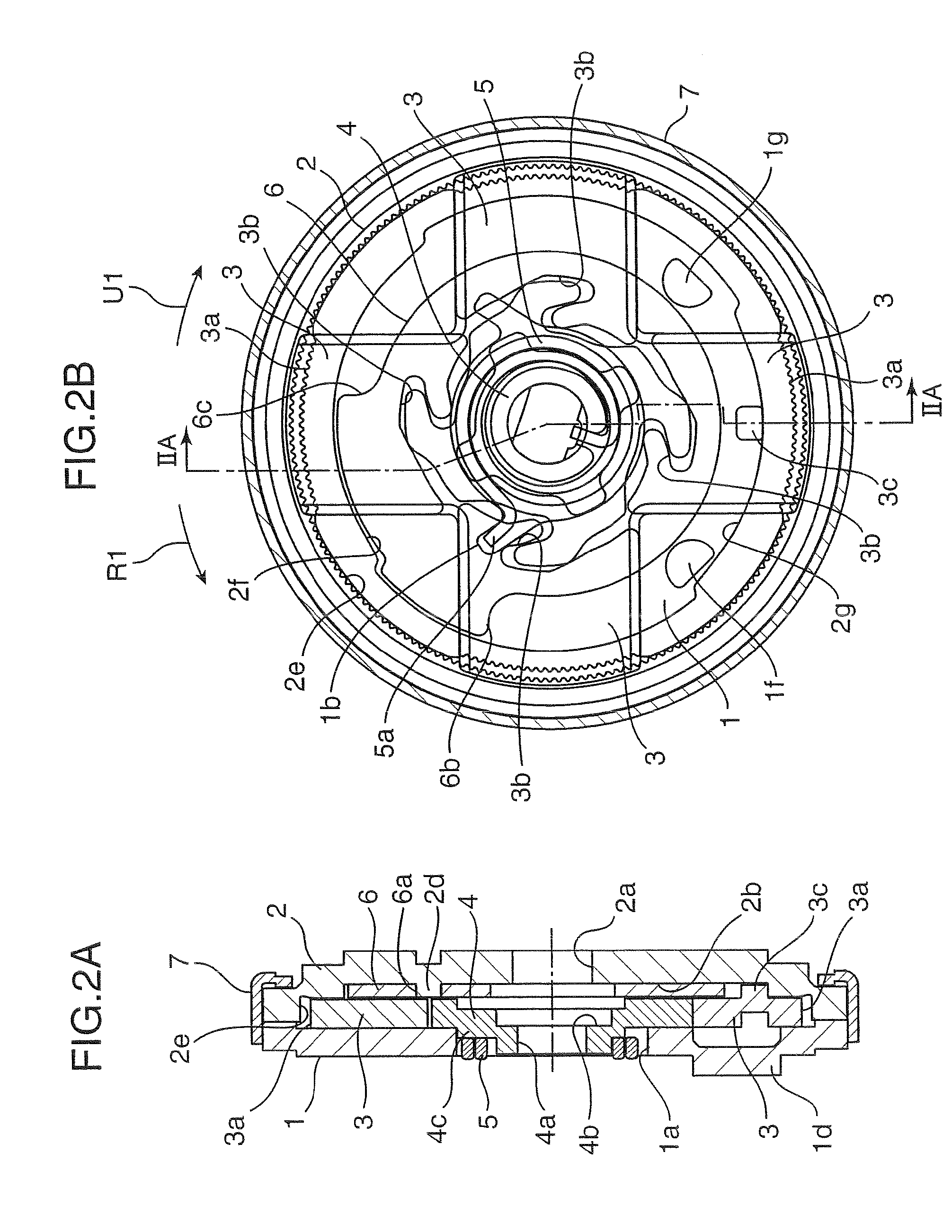
[0035]As shown in FIGS. 1, 2A and 2B, a seat reclining mechanism according to one embodiment of the present invention is designed to be mounted to a seat cushion and a seat back of a seat so as to allow the seat back to be reclined. The mechanism comprises a guide bracket 1 adapted to be mounted to the seat cushion, an internal gear member 2 adapted to be mounted to the seat back, four lock gear members 3, a rotatable cam 4, a lock spring 5, a stopper plate 6, and a ring 7.

[0036]As shown in FIGS. 3A and 3B, the guide bracket 1 is formed in a circular disk shape. The guide bracket 1 has a fitting portion which comprises a fitting hole 1a concentrically formed in the guide bracket 1. The fitting hole 1a includes a cutout 1b formed to lock an outer end 5a of the lock spring 5 which is a spiral spring.

[0037]The guide bracket 1 has four guide grooves 1c w...


PUM


Abstract

A seat reclining mechanism comprises a plurality of lock gear members. One of the plurality of lock gear members has a protrusion which protrudes toward an internal gear member. The internal gear member has a first free-zone arc portion formed along a circle having a center on a rotation axis and adapted to allow the protrusion to be in contact therewith when the lock gear members are located at a position where external teeth of each of lock gear members are not in meshing engagement with internal teeth of the internal gear, and a second free-zone arc portion formed along the circle to have an arc length different from that of the first free-zone arc portion and adapted to allow the protrusion to be in contact therewith when the lock gear members are located at the position.

Description

BACKGROUND OF THE INVENTION[0001]1. Field of the Invention[0002]The present invention relates to a seat reclining mechanism.[0003]2. Description of the Related Art[0004]Heretofore, there has been known a seat reclining mechanism designed to be mounted to a seat cushion and a seat back so as to allow the seat back to be reclined. JP 2001-17259A and JP 2004-154585A disclose a reclining mechanism which comprises a guide bracket adapted to be mounted to either one of a seat cushion and a seat back, an internal gear member (i.e., internally-toothed gear member) adapted to be mounted to a remaining one of the seat cushion and the seat back, a plurality of lock gear members disposed between the guide bracket and the internal gear member and adapted to be slidingly guided in a radial direction, a rotatable cam adapted to move the lock gear members in both a lock direction causing the lock gear members to be brought into engagement with the internal gear member and an unlock direction causin...

Claims


Application Information

Patent Timeline
IPC IPC(8): B60N2/235
CPCB60N2/2356B60N2/236
Inventor TARUSAWA, MAKOTOOKI, YASUKAZUHAYASHI, TOSHINORI
Owner DELTA KOGYO CO LTD
Why Eureka
Try Eureka