
Autonomous outer loop control of man-rated fly-by-wire aircraft

a fly-by-wire aircraft and autonomous control technology, applied in the field of flight control systems, can solve the problems of aircraft losing life, nose pitching upward, aircraft prone to lose airspeed,

Inactive Publication Date: 2009-06-23
CALSPAN CORP
View PDF8 Cites 18 Cited by
  • Summary
  • Abstract
  • Description
  • Claims
  • Application Information

AI Technical Summary

Benefits of technology

This approach allows for the conversion of fly-by-wire aircraft into UAVs without the need for extensive reprogramming or replacing the flight control processor, reducing costs and simplifying the process by using existing systems and interfaces, ensuring reliable and safe operation.

Problems solved by technology

For example, if the pilot adjusts the control stick aft, the elevators will cause the nose to pitch upward and the aircraft will tend to lose airspeed.
The system's reliability and redundancy ensures that there is a very low probability of failure and the resulting loss of the aircraft and life due to a control system malfunction.
Unfortunately, the fleet of available F-4 aircraft is dwindling and the supply of F-4 aircraft will soon be depleted.
However, both of these approaches have their drawbacks.
Reprogramming or replacing the original man-rated flight control processor is a complex and costly proposition.
The fact that most of the fly-by-wire aircraft expected to be used for this application are now more than 20 years old further complicates matters.
The system design and test definitions for these functions have been lost over time.
Accordingly, the effort required to replicate and prove a replacement system having identical fit / form / function and repeat the required development testing has been found to be prohibitively expensive.

Method used


Image

  • Autonomous outer loop control of man-rated fly-by-wire aircraft
  • Autonomous outer loop control of man-rated fly-by-wire aircraft
  • Autonomous outer loop control of man-rated fly-by-wire aircraft

Examples


Embodiment Construction

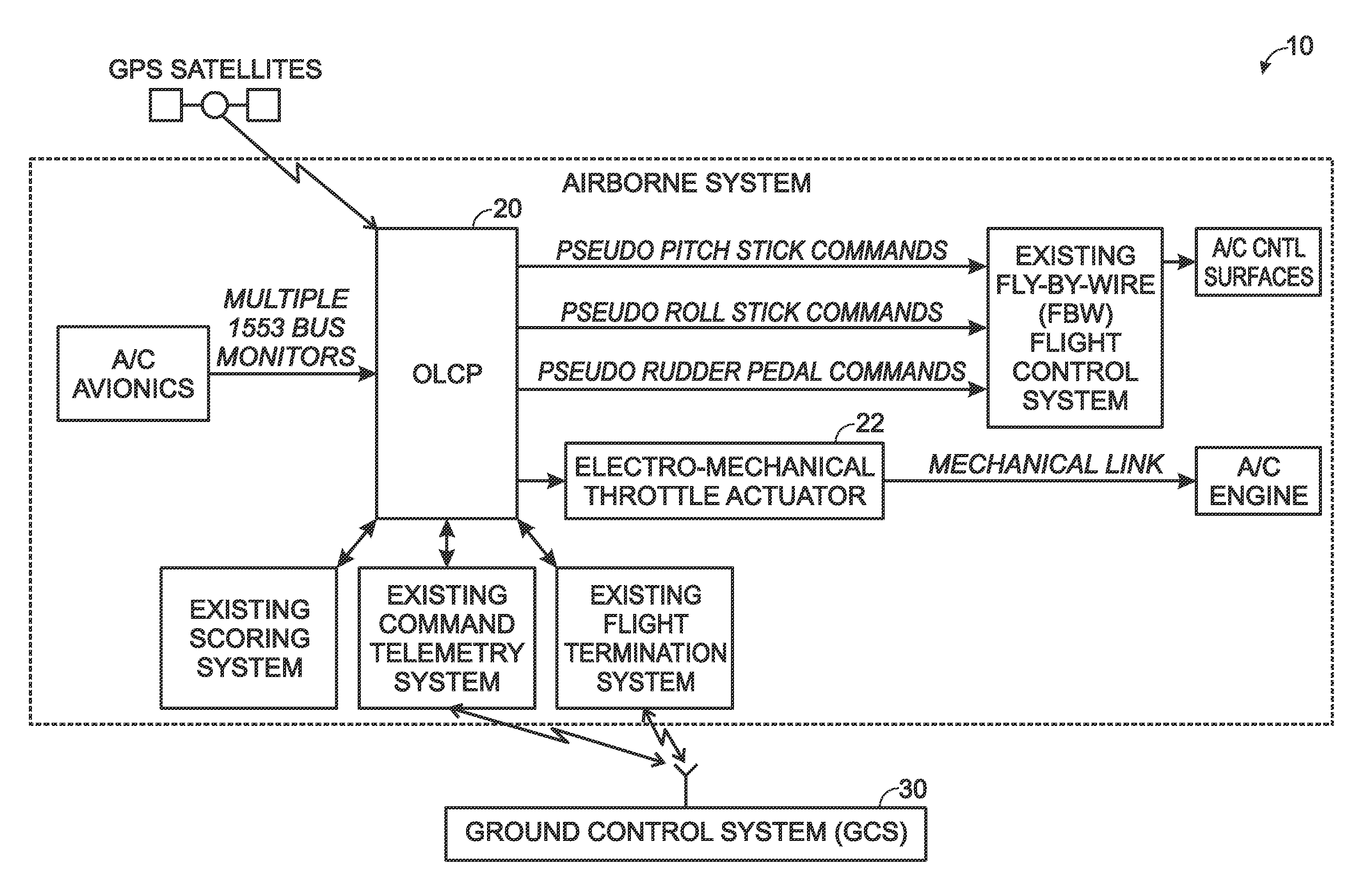
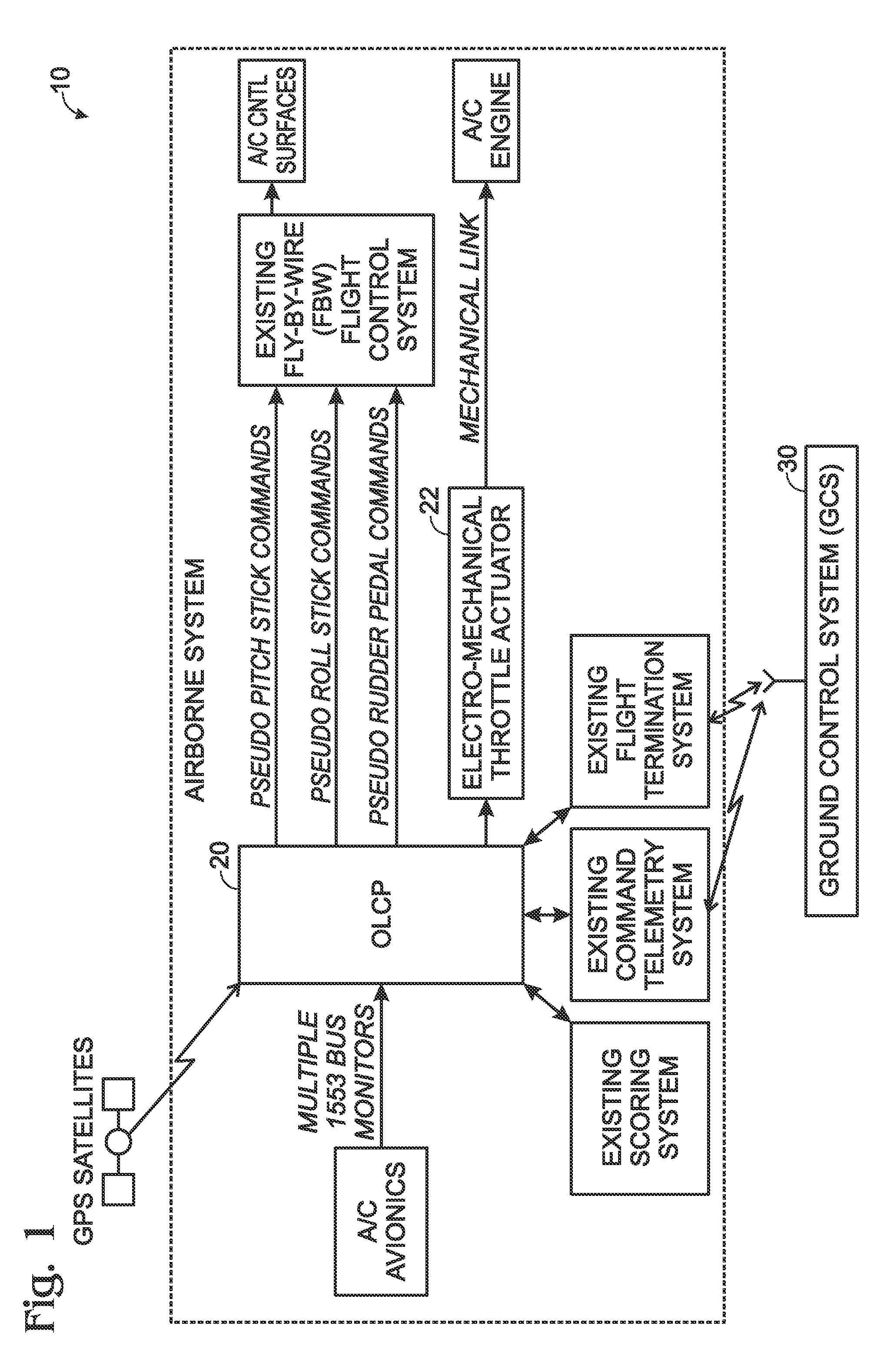
[0029]Reference will now be made in detail to the present exemplary embodiments of the invention, examples of which are illustrated in the accompanying drawings. Wherever possible, the same reference numbers will be used throughout the drawings to refer to the same or like parts. An exemplary embodiment of the system of the present invention is shown in FIG. 1, and is designated generally throughout by reference numeral 10.

[0030]As embodied herein, and depicted in FIG. 1, a block diagram of a UAV control system 10 in accordance with one embodiment of the present invention is disclosed. The system 10 includes an outer loop control platform (OLCP) 20 disposed on an airborne platform, and a ground control system (GCS) 30. Those of ordinary skill in the art will understand that GCS 30 may also be implemented on an airborne platform depending on mission requirements.

[0031]Although not shown in FIG. 1, GCS 30 typically includes communications and telemetry systems that are adapted to comm...


PUM


Abstract

The present invention is directed to a control system for use on a fly-by-wire (FBW) aircraft. The system includes a controller coupled to the FBW aircraft. The controller is configured to generate a plurality of simulated pilot control signals from at least one aircraft maneuver command. The plurality of simulated pilot control signals are generated in accordance with a predetermined control law. The at least one aircraft maneuver command is derived from at least one command telemetry signal received from a remote control system not disposed on the FBW aircraft. The plurality of simulated pilot control signals are configured to direct the FBW aircraft to perform an aircraft maneuver in accordance with the at least one aircraft maneuver command.

Description

BACKGROUND OF THE INVENTION[0001]1. Field of the Invention[0002]The present invention relates generally to flight control systems, and particularly to fly-by-wire flight control systems for unmanned airborne vehicles (UAVs).[0003]2. Technical Background[0004]The market for UAVs is growing and is in the range of several billion dollars per year. UAVs may be used for many purposes including aerial surveillance, weapons delivery, and target training. Many UAVs are used as target drones by providing military pilots with realistic, high performance targets during airborne training. Irregardless of the use, one method for making a UAV is by converting a retired man-rated aircraft into an unmanned vehicle that is remote controlled or preprogrammed to follow a predetermined trajectory. The process of conversion typically involves modifying the retired aircraft's flight control system. A discussion of basic aircraft terminology may be useful before presenting some of the conventional approac...

Claims


Application Information

Patent Timeline
Patent Type & Authority Patents(United States)
IPC IPC(8): B64C13/20
CPCG05D1/0038
Inventor KNOTTS, LOUIS H.OHMIT, ERIC E.
Owner CALSPAN CORP
Learn More