Debris collection system for a planer
a technology for a planer and a collection system, which is applied in the direction of woodworking safety devices, flat surfacing machines, manufacturing tools, etc., can solve the problems of not being able to effectively mix the air flow with the shavings or chips, and the removal of shavings or chips from the cutting area of the planer
- Summary
- Abstract
- Description
- Claims
- Application Information
AI Technical Summary
Benefits of technology
Problems solved by technology
Method used
Image
Examples
first embodiment
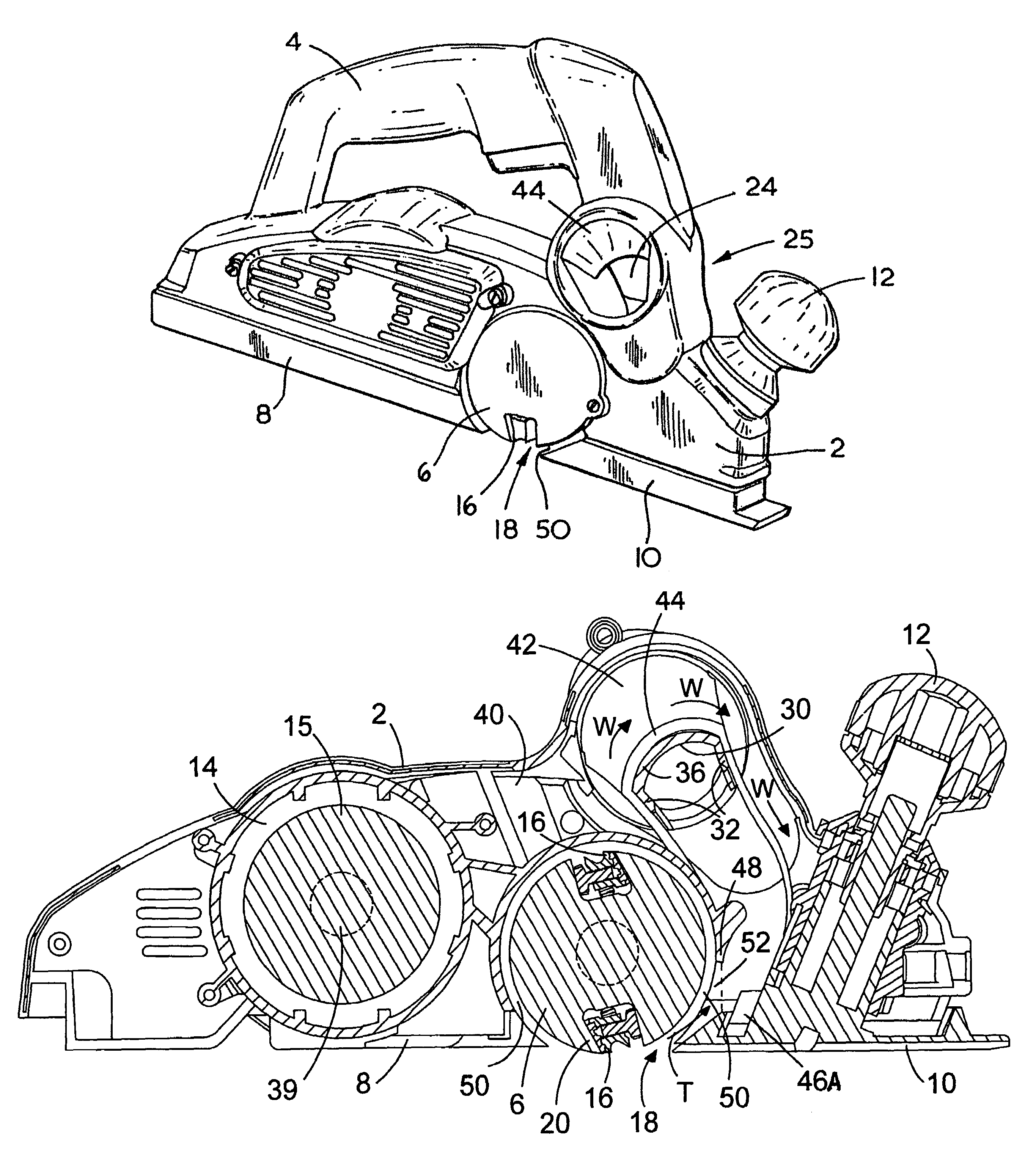
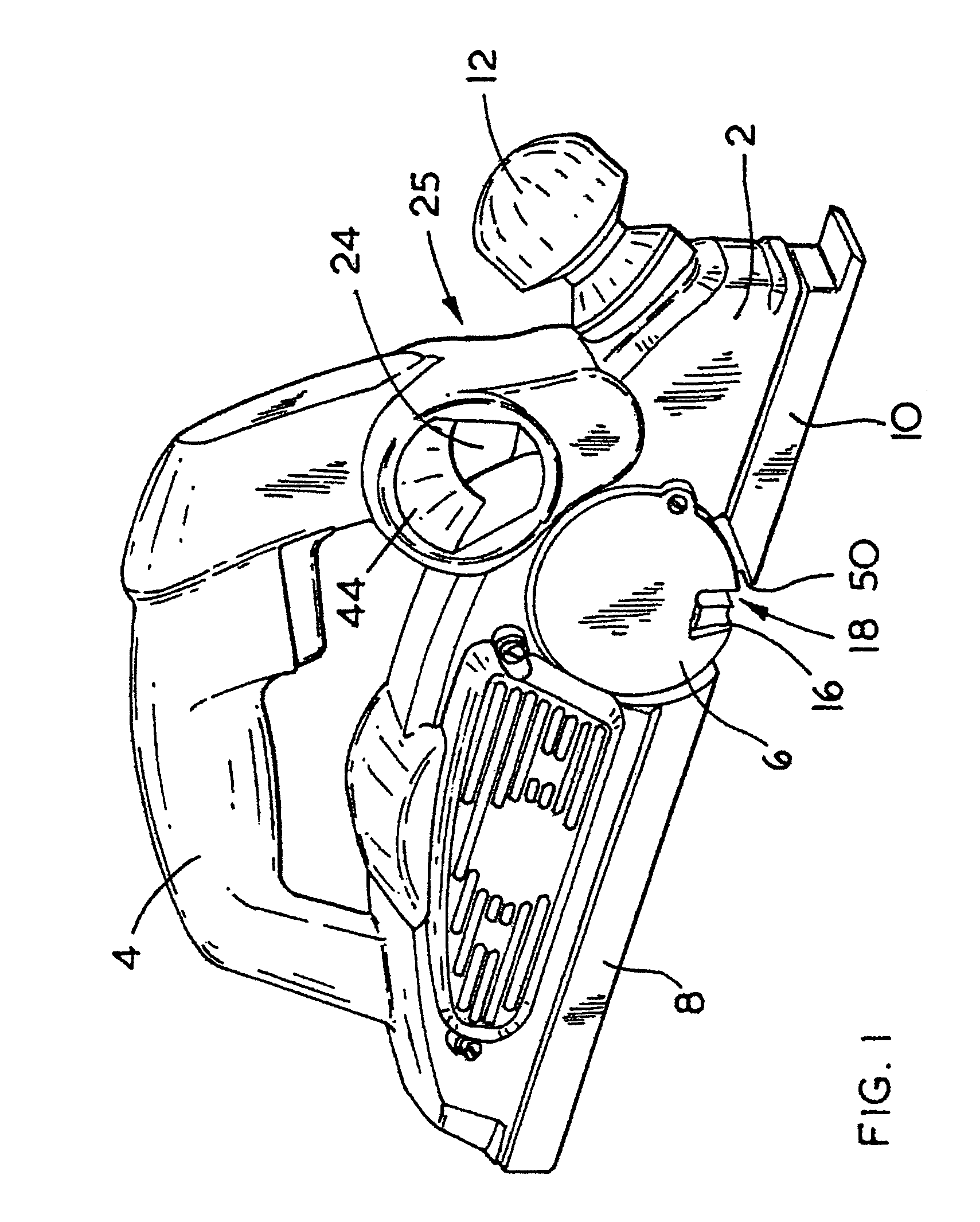
[0031]the planer will now be described with reference to FIGS. 1 to 5. The planer comprises a body 2 having a handle 4 attached to the top of the body 2. A cutting drum 6 is rotatingly mounted within a recess 50 in the body 2 of the planer. The body 2 of the planer is mounted on a shoe formed from two pieces 8, 10. The rear part 8 is mounted rearwardly of the drum 6. The forward part 10 is mounted forward of the drum 6. An aperture 18 in the shoe is formed by the front 10 and rear sections of the shoe through which part of the periphery 20 of the cutting drum 6 extends. The height of the forward part 10 of the shoe can be adjusted in relation to the body 2 by the rotation of a knob 12 mounted on the front of the body 2 of the planer. The operation of the knob 12 is well known and will not therefore be discussed any further.
[0032]Mounted within a cavity 14 of the body 2 of the planer is an electric motor (not shown). The electric motor rotatingly drives the cutting drum 6 via a drive...
second embodiment
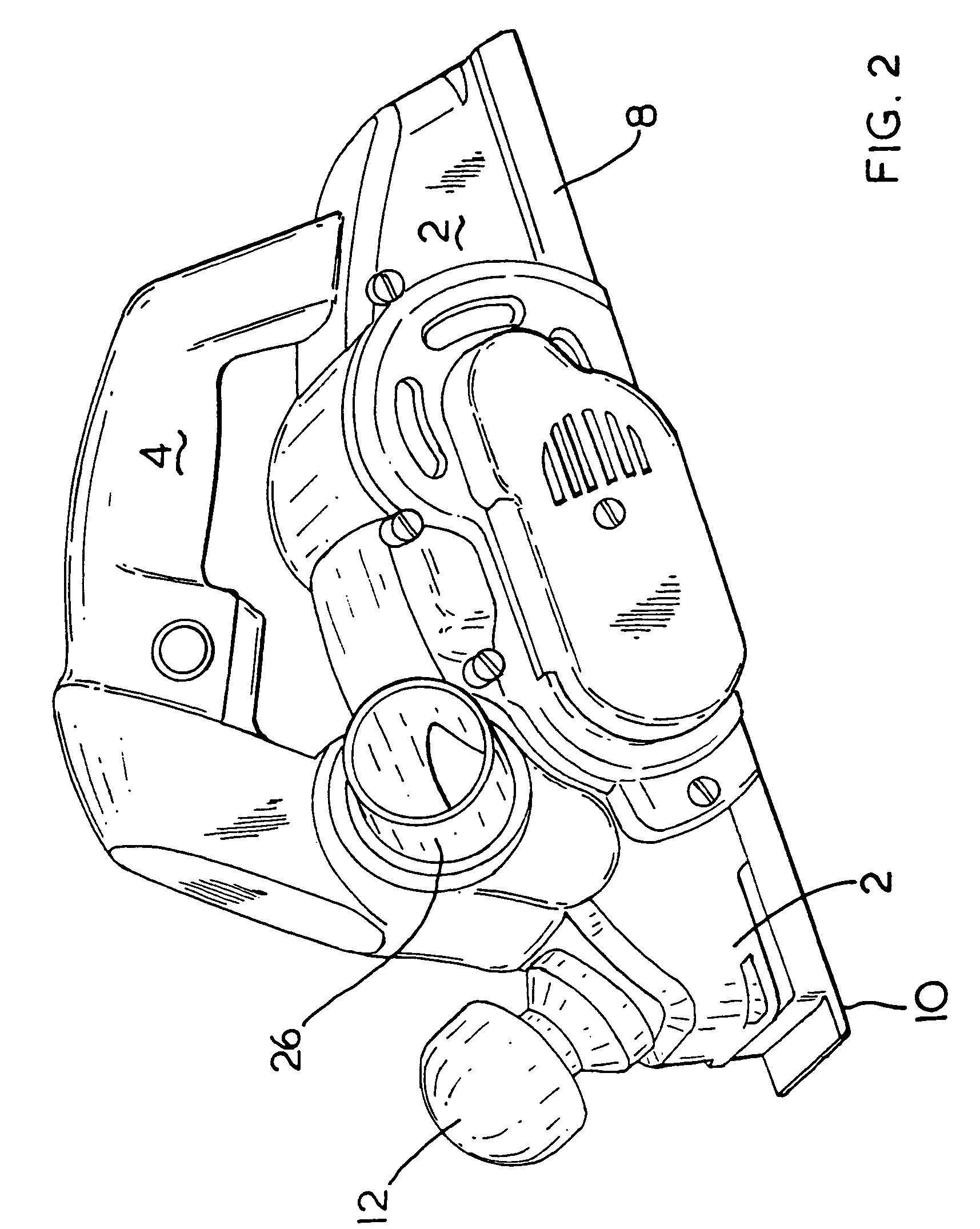
[0039]Because the deflector 26 is angled downwardly by the angle 35 of the rib 38 being non perpendicular to the longitudinal axis 33 of the deflector, a large cavity is formed above the deflector 26 allowing air to easily pass over the top of the deflector 26. FIG. 15 shows a planer according to the The curve section 30 can be seen through the entrance of the exhaust aperture 24.
[0040]A third embodiment of the planer will now be described with reference to FIG. 16. Where the same features are shown in third embodiment as those in the first, the same reference numbers have been used. The third embodiment is exactly the same as the first embodiment except that a vent or nozzle 56 has been added within the body above the port 46A in the body 2 forward of the wall 48 of the recess 50 in which the drum 6 is mounted. The nozzle 56 directs air into the path of the air with entrained debris at an acute angle approximately at the same height as the top of the expulsion aperture 52 formed i...
PUM
 Abstract
Description
Claims
Application Information
 - R&D
- Intellectual Property
- Life Sciences
- Materials
- Tech Scout
- Unparalleled Data Quality
- Higher Quality Content
- 60% Fewer Hallucinations
Browse by: Latest US Patents, China's latest patents, Technical Efficacy Thesaurus, Application Domain, Technology Topic, Popular Technical Reports.
© 2025 PatSnap. All rights reserved.Legal|Privacy policy|Modern Slavery Act Transparency Statement|Sitemap|About US| Contact US: help@patsnap.com


