Eureka AIR delivers breakthrough ideas for toughest innovation challenges, trusted by R&D personnel around the world.

Glaucoma implant having MEMS flow module with flexing diaphragm for pressure regulation

a technology of glaucoma and implant, which is applied in the field of microfabricated devices, can solve problems such as damage to optic nerves, and achieve the effects of reducing flow resistance, increasing flow, and reducing flow resistan

Inactive Publication Date: 2009-06-09
BECTON DICKINSON & CO
View PDF135 Cites 17 Cited by
  • Summary
  • Abstract
  • Description
  • Claims
  • Application Information

AI Technical Summary

Benefits of technology

[0008]Any appropriate coating may be applied to various surfaces of the MEMS flow module and / or any housing associated therewith, including without limitation a coating that improves biocompatibility, that makes such surfaces more hydrophilic, and / or that reduces the potential for bio-fouling. In one embodiment, a self-assembled monolayer coating (e.g., poly-ethylene-glycol) is applied in any appropriate manner (e.g., liquid or vapor phase, with vapor phase being the preferred technique) to all exposed surfaces of the MEMS flow module and any housing that integrates the MEMS flow module for positioning within the conduit.
[0032]Consider again the case where the second plate is spaced from the first plate in a first direction for the fourth embodiment of the MEMS flow module. The MEMS flow module may be oriented so that the first plate is on the high-pressure side of the MEMS flow module and so that the second plate is on the low-pressure side of the MEMS flow module. The second region of the second plate (e.g., an “inner” region) may flex at least generally in the first direction (or away from the first plate) in response to the development of at least a certain differential pressure across the MEMS flow module to change at least one dimension of the first flow restriction and / or decrease the flow resistance of the first flow restriction in a manner that accommodates an increased flow or flow rate through the MEMS flow module. The entire first plate may be at least substantially maintained in a fixed orientation (e.g., such that the entire first plate does not flex or otherwise change shape to any significant degree), or the second region of the first plate (e.g., an “inner” region) could also flex to at least a certain degree in the first direction, but not to the same extent as the second plate. Flexing of the first plate in this manner will still allow for a change in at least one dimension of the first flow restriction and / or a decrease in the flow resistance of the first flow restriction in a manner that accommodates an increased flow or flow rate through the MEMS flow module, but not to the same degree when compared to when the entire first plate remains in an at least substantially fixed orientation.
[0033]The fourth embodiment of the MEMS flow module could also be oriented so that the second plate is on the high-pressure side of the MEMS flow module and so that the first plate is on the low-pressure side of the MEMS flow module. The second region of the first plate (e.g., an “inner” region) may flex at least generally in a second direction that is opposite of the first direction (e.g., to move at least generally away from the second plate) in response to the development of at least a certain differential pressure across the MEMS flow module to change at least one dimension of the first flow restriction and / or decrease the flow resistance of the first flow restriction in a manner that accommodates an increased flow or flow rate through the MEMS flow module. The entire second plate may be at least substantially maintained in a fixed orientation (e.g., such that the entire second plate does not flex or otherwise change shape to any significant degree), or the second region of the second plate (e.g., an “inner” region) could also flex to at least a certain degree in the second direction, but not to the same extent as the first plate. Flexing of the second plate in this manner will still allow for a change in at least one dimension of the first flow restriction and / or a decrease in the flow resistance of the first flow restriction in a manner that accommodates an increased flow or flow rate through the MEMS flow module, but not to the same degree when compared to when the entire second plate remains in an at least substantially fixed orientation.
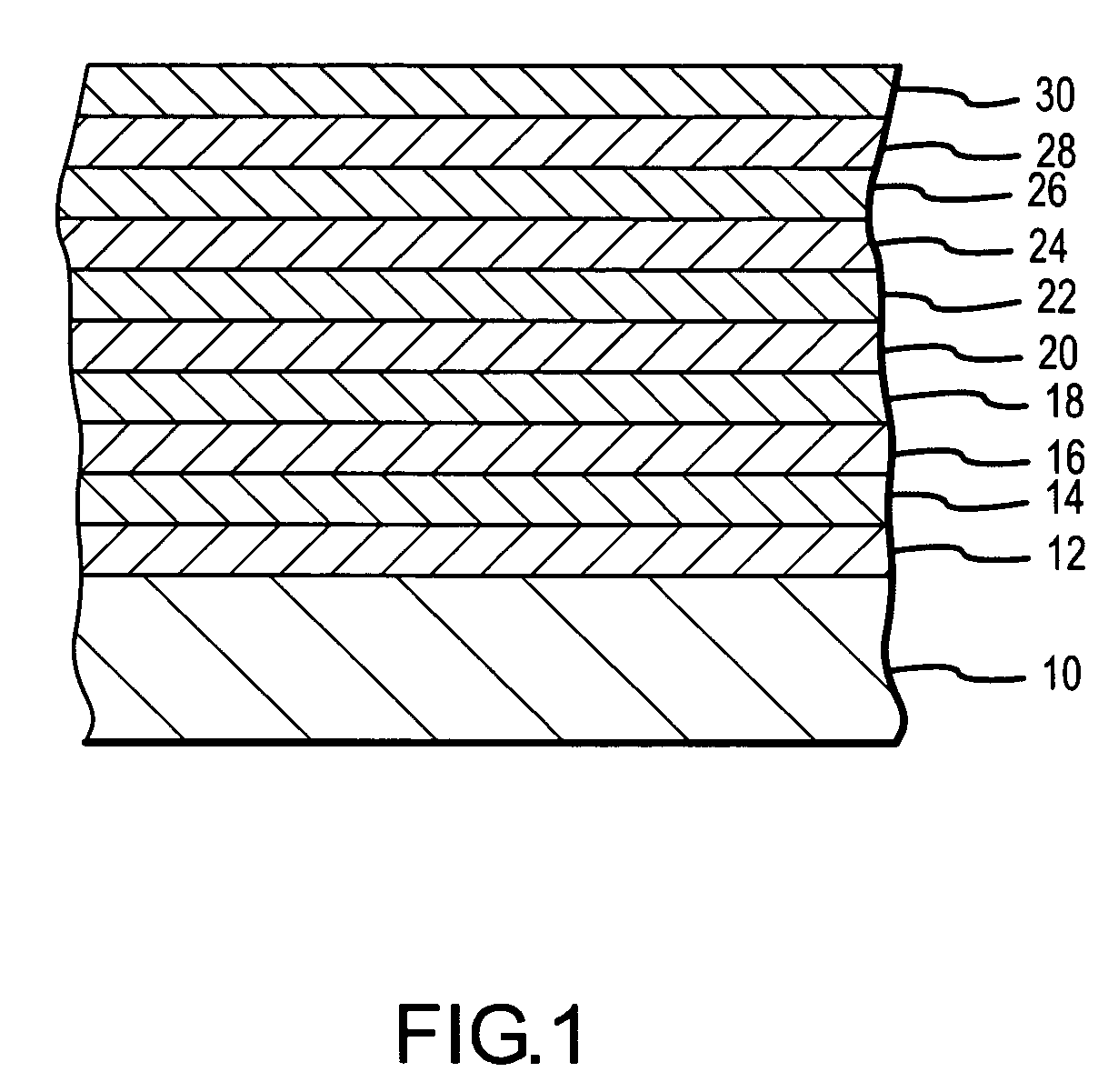
[0045]Various techniques may be employed to increase the rigidity of the first and / or second plate, for instance such that it remains in an at least substantially fixed orientation (e.g., such that it does not flex or otherwise change shape to any significant degree) when the MEMS flow module is exposed to the anticipated differential pressures. Two or more structural layers or films from adjacent fabrication levels could also be disposed in direct interfacing relation (e.g., one directly on the other) to increase the rigidity of the first and / or second plate. Over the region that is to define the first plate or second plate, this would require removal of at least some of the sacrificial material that is deposited on the structural material at one fabrication level before depositing the structural material at the next fabrication level (e.g. sacrificial material may be encased by a structural material, so as to not be removed by the release). Another option for increasing the rigidity of the first and / or second plate would be to maintain the separation between structural layers or films in different fabrication levels for the first plate and / or second plate, but provide an appropriate structural interconnection therebetween (e.g., a plurality of columns, posts, or the like extending between a third plate in a third fabrication level and either the first or second plate).

Problems solved by technology

High internal pressure within the eye can damage the optic nerve and lead to blindness.
There are a number of issues with implants of this type.

Method used


Image

  • Glaucoma implant having MEMS flow module with flexing diaphragm for pressure regulation
  • Glaucoma implant having MEMS flow module with flexing diaphragm for pressure regulation
  • Glaucoma implant having MEMS flow module with flexing diaphragm for pressure regulation

Examples


Embodiment Construction

[0074]The present invention will now be described in relation to the accompanying drawings that at least assist in illustrating its various pertinent features. Generally, the devices described herein are microfabricated. There are a number of microfabrication technologies that are commonly characterized as “micromachining,” including without limitation LIGA (Lithographie, Galvonoformung, Abformung), SLIGA (sacrificial LIGA), bulk micromachining, surface micromachining, micro electrodischarge machining (EDM), laser micromachining, 3-D stereolithography, and other techniques. Hereafter, the term “MEMS device,”“microfabricated device,” or the like means any such device that is fabricated using a technology that allows realization of a feature size of 10 microns or less. Any appropriate microfabrication technology or combination of microfabrication technologies may be used to fabricate the various devices to be described herein.

[0075]Surface micromachining is currently the preferred fab...


PUM


Abstract

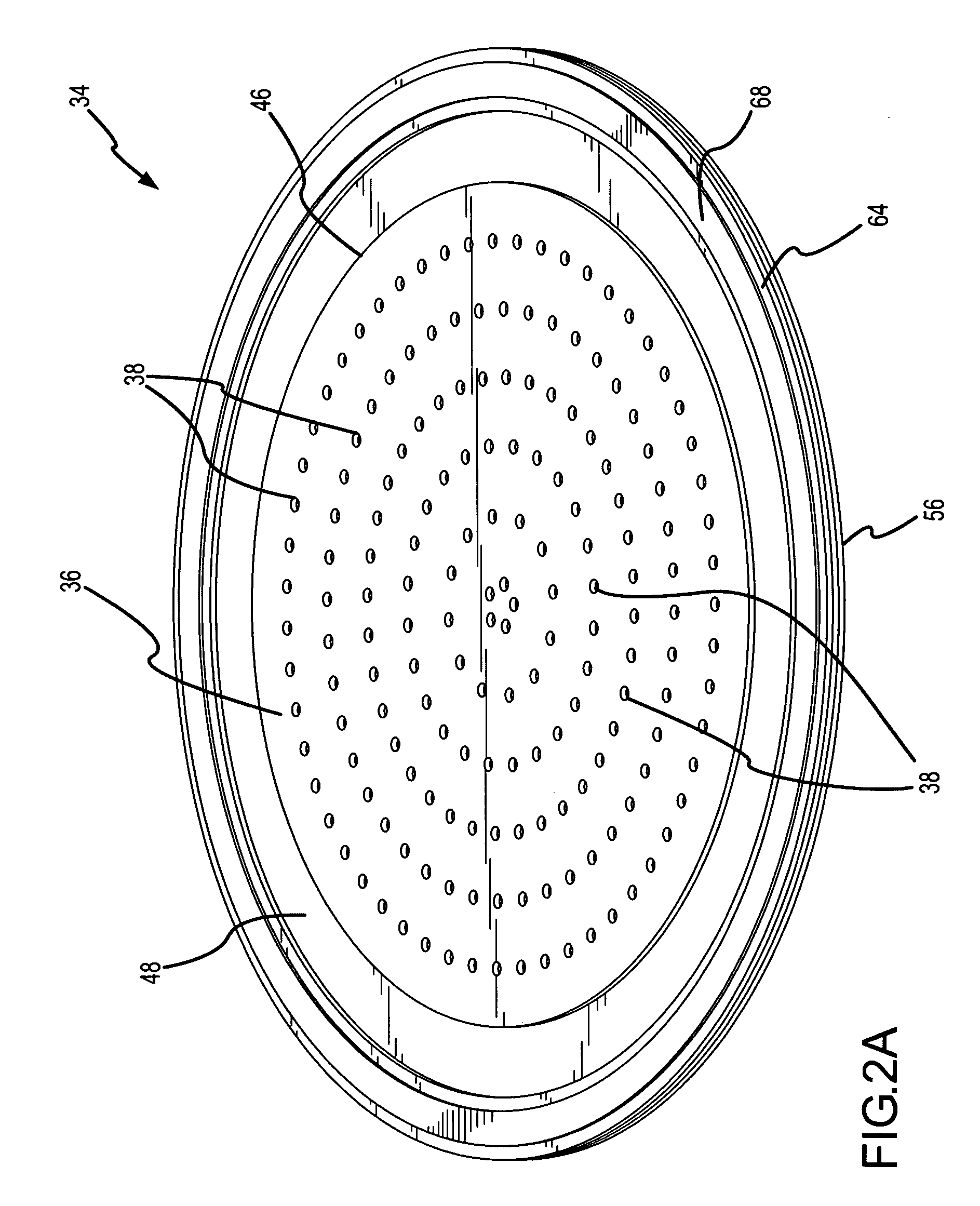
One embodiment of a MEMS flow module (34) includes a first plate (36) and a second plate (48) that are separated by a first link (62). A plurality of concentrically disposed, annular flow-restricting walls (40) extend from the first plate (36), and each is separated from the second plate (48) by a flow-restricting gap (58). When the MEMS flow module (34) is exposed to a differential pressure and in one configuration, a perimeter (46) of the first plate (36) flexes away from the second plate (48) (and at least generally about where the first link (62) interfaces with the first plate (36)) to increase the size of one or more of the flow-restricting gaps (58), to in turn accommodate an increased flow or flow rate through the MEMS flow module (34).

Description

FIELD OF THE INVENTION[0001]The present invention generally relates to the field of microfabricated devices and, more particularly, to an implant having a MEMS flow module that utilizes a flexing diaphragm to provide at least a pressure regulation function.BACKGROUND OF THE INVENTION[0002]High internal pressure within the eye can damage the optic nerve and lead to blindness. There are two primary chambers in the eye—an anterior chamber and a vitreous body that are generally separated by a lens. Aqueous humor exists within the anterior chamber, while vitreous humor exists in the vitreous body. Generally, an increase in the internal pressure within the eye is caused by more fluid being generated within the eye than is being discharged by the eye. The general consensus is that it is excess fluid within the anterior chamber of the eye that is the main contributor to an elevated intraocular pressure.[0003]One proposed solution to addressing high internal pressure within the eye is to ins...

Claims


Application Information

Patent Timeline
Patent Type & Authority Patents(United States)
IPC IPC(8): A61M5/00B01D63/00
CPCA61F9/00781B82Y30/00B33Y80/00
Inventor RODGERS, M. STEVENSNIEGOWSKI, JEFFRY J.MCWHORTER, PAUL J.
Owner BECTON DICKINSON & CO
Why Eureka
Eureka Blog
Learn More