
Device for a line termination of two-wire lines

a two-wire line and device technology, applied in the field of two-wire line termination devices, can solve problems such as inflexibility in use, and achieve the effects of reducing costs, reducing expenditure, and reducing costs for customers and suppliers

Inactive Publication Date: 2009-06-02
ROBERT BOSCH GMBH
View PDF17 Cites 47 Cited by
  • Summary
  • Abstract
  • Description
  • Claims
  • Application Information

AI Technical Summary

Benefits of technology

This configuration minimizes the need for multiple control units, reduces logistics and costs, and allows for adaptable termination resistors in various applications, enhancing flexibility and efficiency.

Problems solved by technology

As a consequence, there is no flexibility in use.

Method used


Image

  • Device for a line termination of two-wire lines
  • Device for a line termination of two-wire lines

Examples


Embodiment Construction

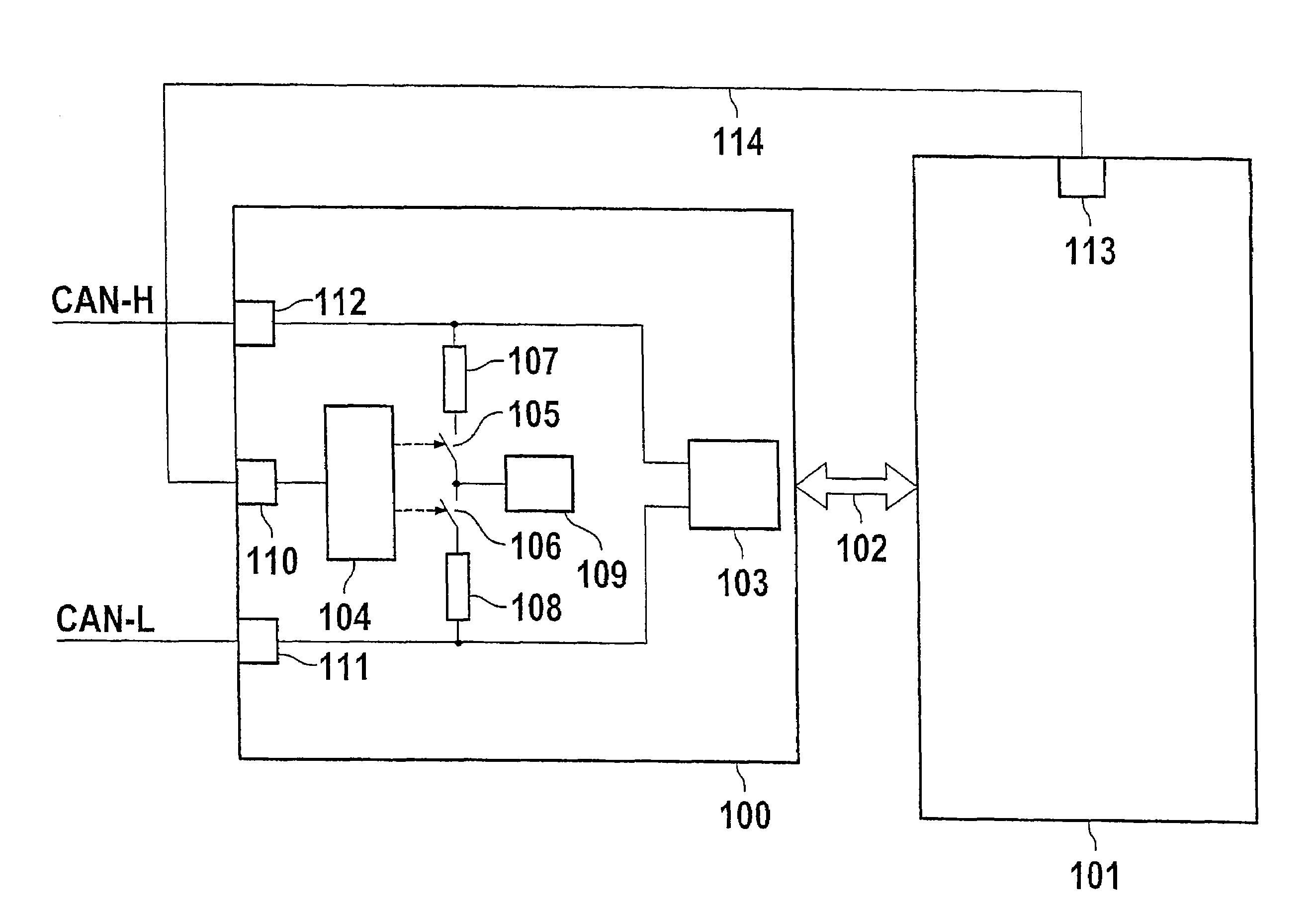
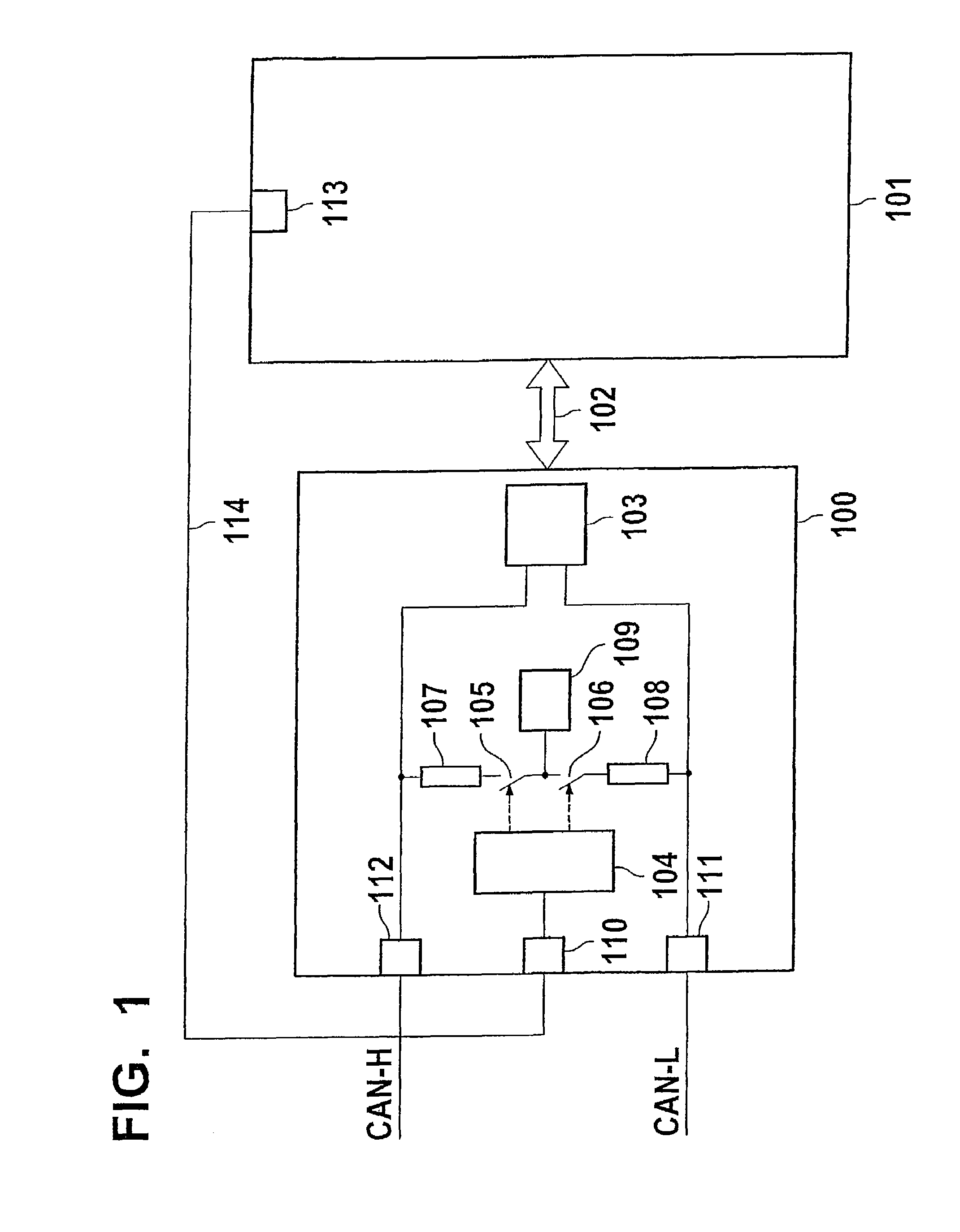
[0014]The single FIGURE—FIG. 1—shows a CAN high and a CAN low line, CAN-H and CAN-L, respectively, which are connected to a component 100 via coupling elements 111 and 112, respectively, which component 100 functions as a CAN transceiver, that is, component 100 assumes the receive and / or transmit functionality, i.e., the transceiver function of a CAN component in this respect. The CAN-High and CAN-Low lines are guided to a driver module, in particular a CAN driver module 103. Furthermore, two terminating resistors 107 and 108 are shown, which are connected in series and, with the aid of switching means 105 and 106, are able to be connected to one another and also to a balancing unit, i.e., a balancing element 109. Switching means 105 and 106 are addressed by a control logic 104, which action is symbolically denoted by the dashed arrows. The control logic 104 itself receives an input signal via line 114 and an additional coupling element 110, for instance from an output 113 of the ar...


PUM


Abstract

A device for a line termination of two-wire lines having at least one first and second terminating resistant between the two wires is provided, the first and the second terminating resistors being connected in series, and at least one switching arrangement being provided between the two terminating resistors.

Description

CROSS-REFERENCE TO RELATED APPLICATIONS[0001]The present application is a continuation of U.S. patent application Ser. No. 10 / 538,526 filed on Dec. 12, 2005, which in turn was a national-phase application based on international application PCT / DE03 / 04133 filed on Dec. 16, 2003, and claimed priority to German Application DE 102 61 386.9 filed on Dec. 30, 2002.FIELD OF THE INVENTION[0002]The present invention relates to a device for a line termination of two-wire lines having a first and second terminating resistor between the two wires, the first and the second terminating resistor being connected in series.BACKGROUND INFORMATION[0003]A device for a line termination of two-wire lines is described in the German patent DE 195 25 350. It is described there that at least one first and one second terminating resistor are provided between the two wires of the two-wire line and that the two resistors be connected in series. Originating with the connecting line between the two resistors is a...

Claims


Application Information

Patent Timeline
Patent Type & Authority Patents(United States)
IPC IPC(8): H03K17/16G11C7/10H03K19/003G06F13/40
CPCG06F13/4086H04L12/40032H04L25/0298H04L2012/40215H04L2012/40273G06F13/40H04B3/50H04L25/02
Inventor FAHRBACH, WILHELMWEYHERSMUELLER, UDO
Owner ROBERT BOSCH GMBH
Learn More