
Vibratory paving screed for a paver

a technology of vibratory paving and paver, which is applied in the direction of roads, roads, constructions, etc., can solve the problems of unevenness, high cost, and difficulty in handling height-adjustable pre-strike-offs, so as to reduce the wear of the baseplate, uniform compaction, and reduce the effect of baseplate wear

Inactive Publication Date: 2009-06-02
ABG ALLG BAUMASCHINEN GMBH
View PDF24 Cites 12 Cited by
  • Summary
  • Abstract
  • Description
  • Claims
  • Application Information

AI Technical Summary

Benefits of technology

"The invention provides a vibratory paving screed for a paver that can achieve satisfactory compaction without the need for a height-adjustable pre-strike-off. This reduces wear and tear on the baseplate, while also improving handling and maintaining layer thickness during paving. The use of a separate, solid strip with a metering slope in the region of its front edge further enhances compaction and improves uniformity even in uneven subgrades."

Problems solved by technology

Without a tamper device, the result is a much more non-uniform compaction in the layer laid by the paver.
This leads, inter alia, to correspondingly large unevenesses following the subsequent rolling operation performed by a compaction roller.
Moreover, height-adjustable pre-strike-offs are very elaborate and expensive and also difficult to handle.
As a result, the baseplates of the paving screed wear very unevenly and thus prematurely.

Method used


Image

  • Vibratory paving screed for a paver
  • Vibratory paving screed for a paver
  • Vibratory paving screed for a paver

Examples


Embodiment Construction

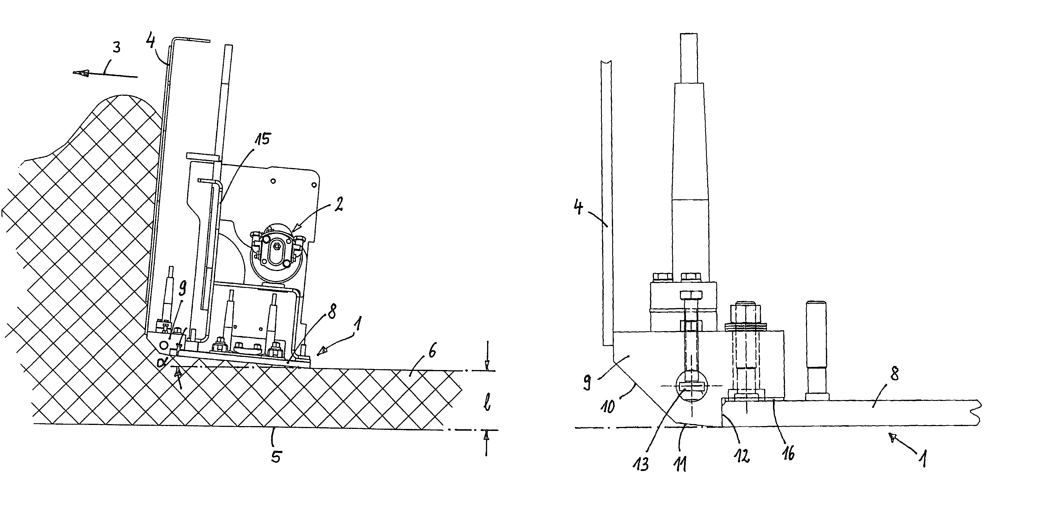
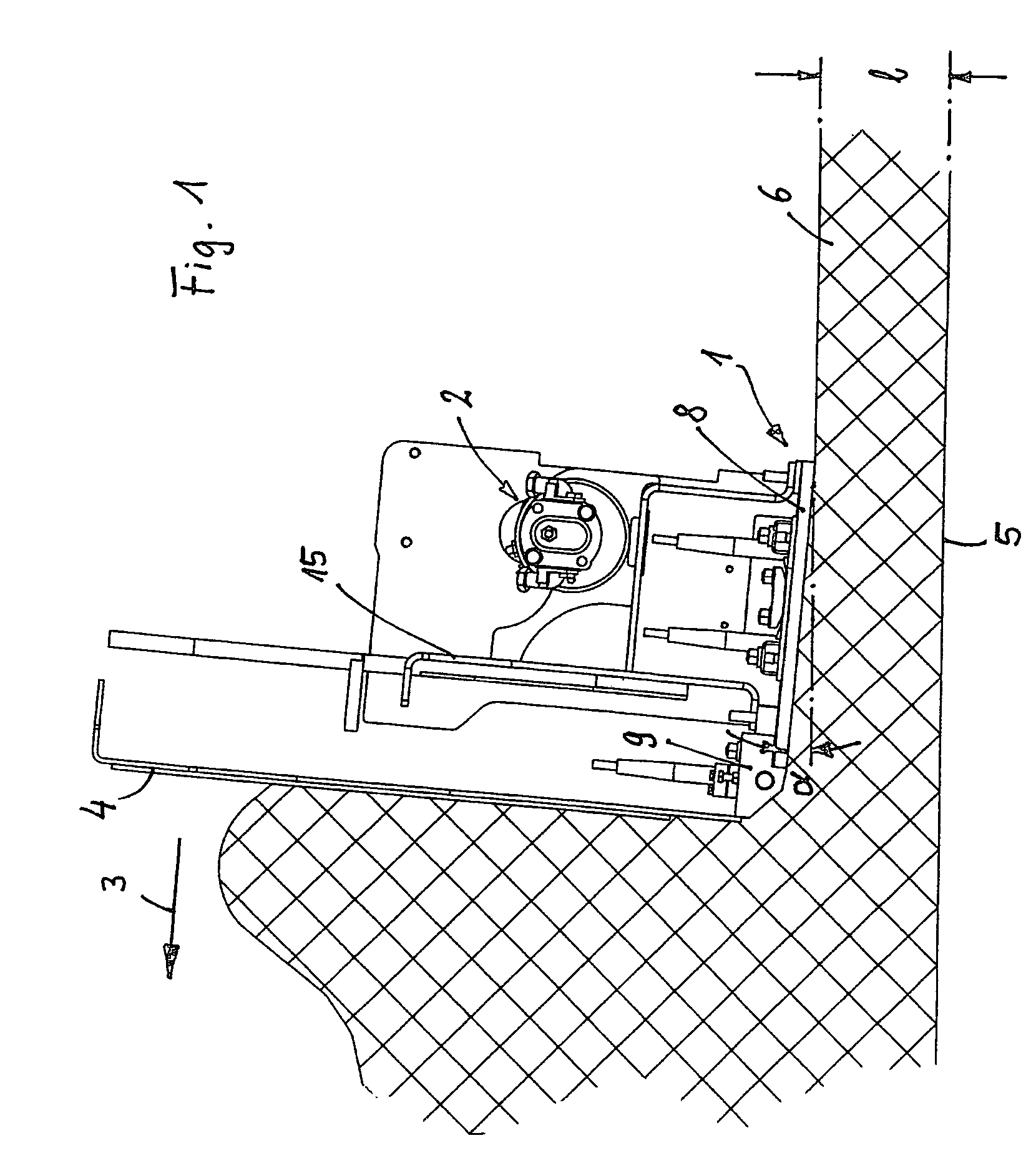
[0015]The tamper-free vibratory paving screed represented schematically in FIG. 1 comprises a baseplate 1 made of steel sheet, which is coupled to a vibration drive 2 situated above it so as to induce vibrations in the—generally heatable—baseplate 1. Situated upstream of the baseplate 1 in the paving direction (arrow 3) is a front wall 4 which is fixed with respect to the baseplate 1 and whose lower edge bears against the front edge of the baseplate 1.

[0016]In the paving situation represented, a paving layer 6 is laid on a subgrade 5 by means of a paver (not shown) provided with the vibratory paving screed. The front of the paver is usually equipped with a hopper for holding paving material which is then conveyed by means of a conveyor towards the rear of its chassis into the region of a distributor auger, which is situated in front of the vibratory paving screed. The vibratory paving screed here is articulated on the chassis via tow arms and floats on the paving material, with the ...


PUM


Abstract

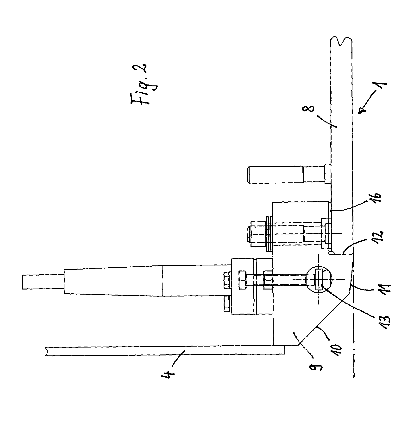
The invention relates to a vibratory paving screed for a paver, comprising a baseplate and a vibration drive therefor and also comprising a front wall which is mounted upstream of the baseplate in the paving direction, is fixed with respect to the baseplate and engages with the baseplate, in which arrangement the baseplate comprises a section of uniform thickness and, in the region of its front edge, a separate, solid strip which is connected to the section and has a metering slope and a flat run-in bevel situated behind.

Description

FIELD OF THE INVENTION[0001]The invention relates to a vibratory paving screed for a paver as it is used for instance for the construction of roads.BACKGROUND OF THE INVENTION[0002]Pavers with a chassis and with a trailed, floating paving screed articulated on this chassis via tow arms, the angle of attack of the paving screed being adjustable with respect to the ground and the paving screed having a pre-strike-off and a baseplate coupled to a vibration drive, are known both without as well as with at least one tamper bar which can move up and down by means of a drive and which has a variable number of strokes (with regard to the latter, cf., for example, German Patent No. DE 198 36 269 C1).[0003]The action of a tamper device in tamping / vibratory paving screeds consists in a metering action which results in a high degree of compaction and in uniform compaction with respect to the mix to be placed. In the metering paving process, excess mix escapes to the front via a slope in the fro...

Claims


Application Information

Patent Timeline
Patent Type & Authority Patents(United States)
IPC IPC(8): E01C19/38
CPCE01C19/40E01C2301/10
Inventor HEIMS, DIRK
Owner ABG ALLG BAUMASCHINEN GMBH
Learn More