


Quick Research
Generate reliable direction feasibility study reports for your R&D in just a few steps.

Technical Q&A
Discover and master advanced knowledge NOW. Basics, ideas, possibilities, all at once.

Find Solutions
As an expert in R&D theories, this can generate solutions to your technical problems instantly.

Evaluate Feasibility
Analyze your overall solution with one click, know your potential R&D risks in advance.

Monitor Landscape
Get weekly tech updates, stay abreast of the latest tech innovations and key insights.
Electrical connector with improved positioning device
a positioning device and electric connector technology, applied in the direction of coupling device connection, coupling device details, incorrect coupling prevention, etc., can solve the problem that the through-hole of the positioning device is not easy to aim at the tail, and achieve the effect of improving the positioning device and being easy to assembled
- Summary
- Abstract
- Description
- Claims
- Application Information
AI Technical Summary
Benefits of technology
Problems solved by technology
Method used
Image

Examples
Embodiment Construction
[0015]Reference will now be made to the drawing figures to describe a preferred embodiment of the present invention in detail.
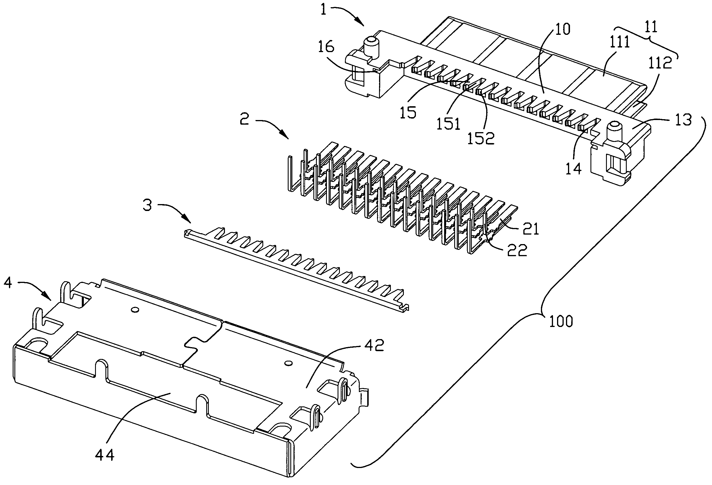
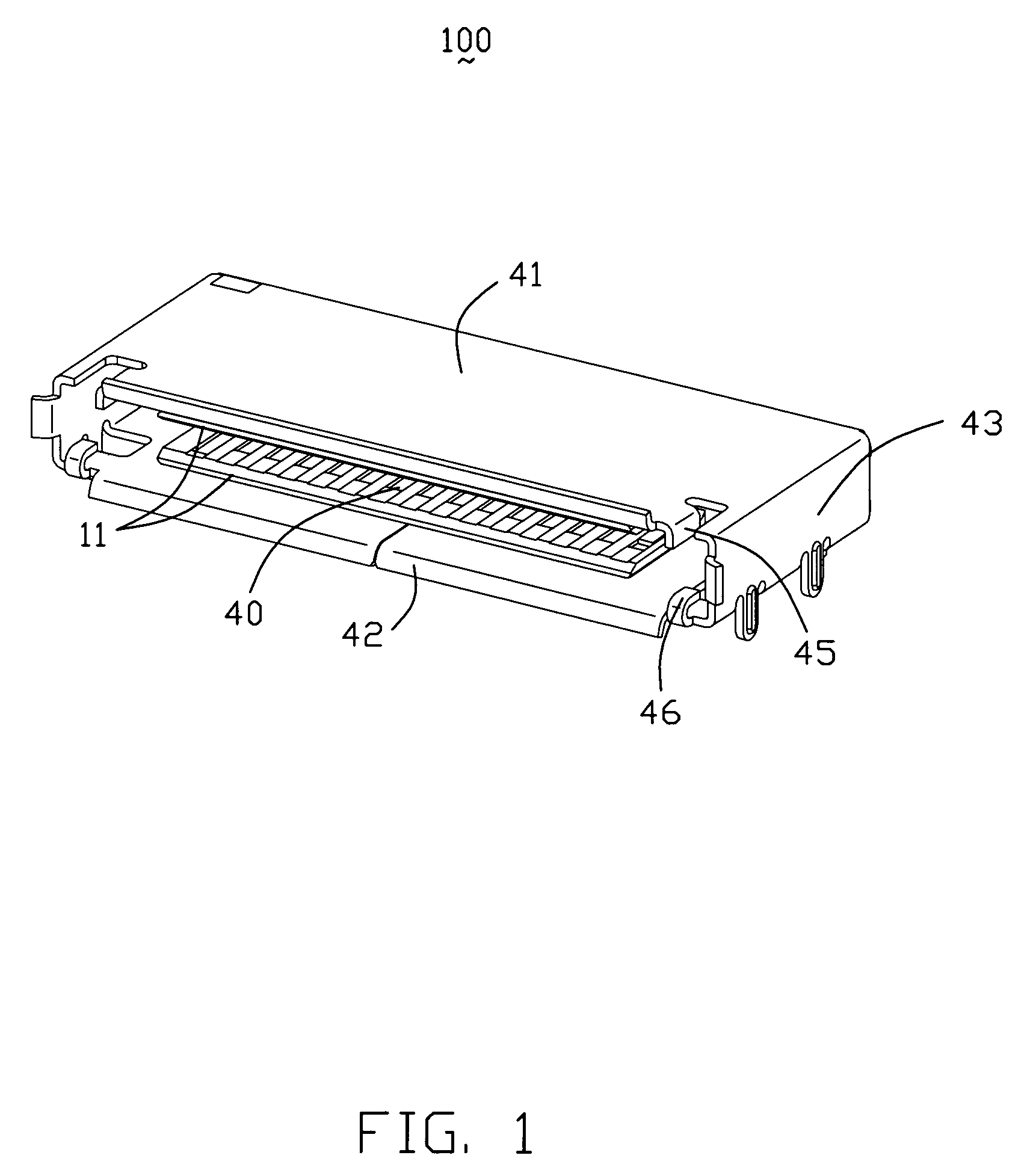
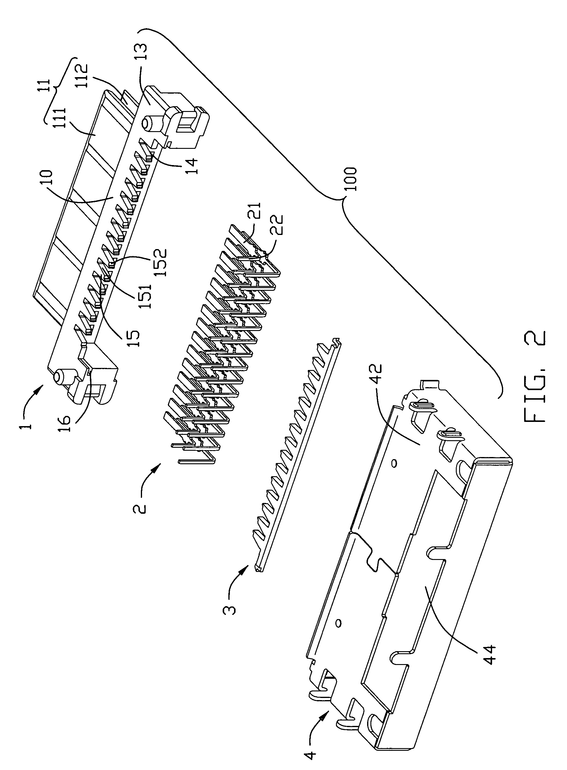
[0016]Referring to FIG. 2, an electrical connector 100 comprises an insulating housing 1, two rows of conductive terminals 2, a positioning device and a shell 4 assembled to the insulating housing 1. The positioning device comprises a first member extending integrally from the housing 1 and a second member 3 provided separately from the housing 1 and cooperating with the first member.
[0017]The insulating housing 1 includes a base portion 10 and a mating portion 11. The base portion 10 has a front end portion and a rear end portion. The mating portion 11 extends from the front end portion of the base portion 10. The mating portion 11 includes an upper tongue plate 111 and a lower tongue plate 112 parallel to the upper tongue plate 111. A plurality of terminal passageways 14 is defined on a lower surface of the upper tongue plate 111 and an upper surface of the...
PUM
 Abstract
Description
Claims
Application Information
 - R&D Engineer
- R&D Manager
- IP Professional
- Industry Leading Data Capabilities
- Powerful AI technology
- Patent DNA Extraction
Browse by: Latest US Patents, China's latest patents, Technical Efficacy Thesaurus, Application Domain, Technology Topic, Popular Technical Reports.
© 2024 PatSnap. All rights reserved.Legal|Privacy policy|Modern Slavery Act Transparency Statement|Sitemap|About US| Contact US: help@patsnap.com