
Continuously variable ratio transmission system

a transmission system and constant-variable technology, applied in the direction of belts/chains/gearrings, mechanical equipment, belts/chains/gearrings, etc., can solve the problem of not being able to achieve maximum power, and achieve the effect of improving the overall economy

Active Publication Date: 2009-05-12
ALLISON TRANSMISSION INC
View PDF4 Cites 31 Cited by
  • Summary
  • Abstract
  • Description
  • Claims
  • Application Information

AI Technical Summary

Benefits of technology

[0007]The variator is the lowest efficiency component of the transmission but it enables engine optimisation by ratio matching, resulting in improved overall economy. However, this is not possible at maximum power since this occurs only at one engine speed. If power loss is important, it may be beneficial to sacrifice variable ratio for best efficiency by removing the influence of the variator and operating it at a fixed ratio.
[0008]The overall result is to potentially avoid a slight reduction in the top speed of the vehicle to which the transmission is fitted.

Problems solved by technology

However, this is not possible at maximum power since this occurs only at one engine speed.

Method used


Image

  • Continuously variable ratio transmission system
  • Continuously variable ratio transmission system
  • Continuously variable ratio transmission system

Examples


Embodiment Construction

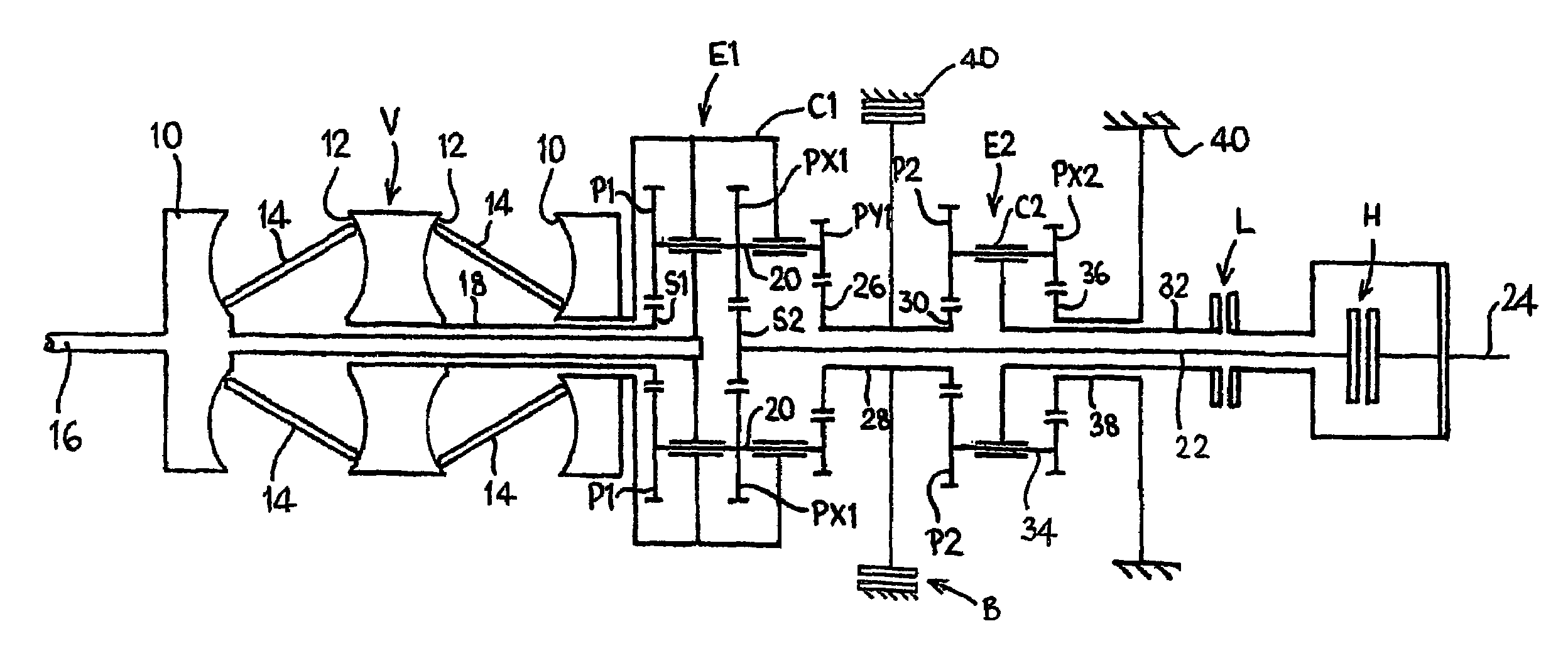
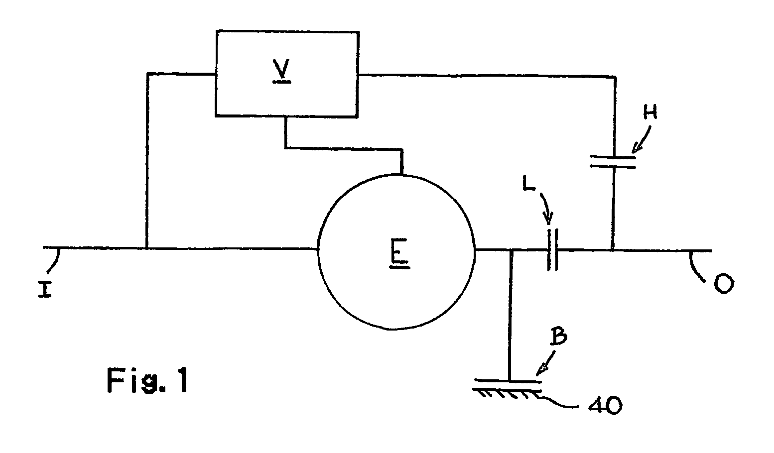
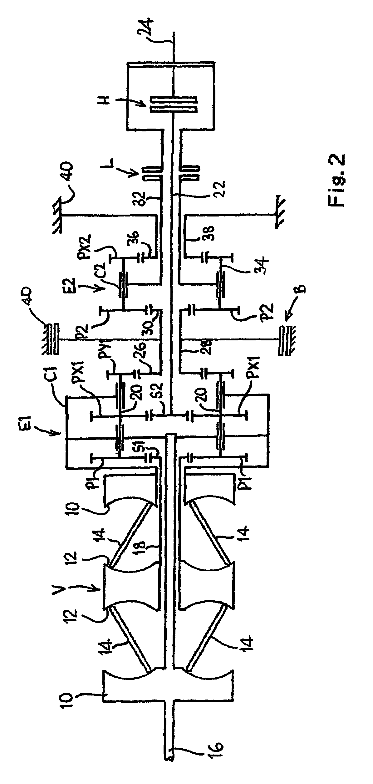
[0025]Referring firstly to FIG. 1, an infinitely variable ratio transmission system comprises a transmission input shaft I and a transmission output shaft O. Connected between the system input shaft I and the system output shaft O is a variator V, preferably of the known toroidal race roller traction type, and a high regime clutch H. The transmission input shaft I and the output of the variator V are also connected to a mixing epicyclic gear set E, the output of which is selectively connectable to the transmission output shaft O by means of a low regime clutch L.

[0026]However, it will also be observed that the output of the epicyclic gear set E can also be locked to the transmission casing 40 by means of a further braking element in the form of clutch B.

[0027]One feature of the output of the mixing epicyclic gear set E is that at a certain variator ratio the output of the epicyclic gear set E is stationary (a condition which, when the transmission is in low regime, is known in the a...


PUM


Abstract

A multiple-regime continuously variable ratio transmission system has a system input shaft (I), a system output shaft (0) and a continuously variable ratio transmission unit (variator) connected to the system input shaft and having a variator output shaft. A first mixing epicyclec gear train (P1) having inputs drivably connected to the variator output shaft (V) and the system input shaft via a first clutch (H) and a second mixing epicyclic gear train having inputs drivably connected to the variator output shaft and the system input shaft has an output (28) connected to a third epicyclic gear train (E2) having an output which is selectively connectable to the to the system output shaft via a first braking element (L). A second braking element (B) is adapted to lock the output (28) of the second mixing epicyclic gear train in a stationary position.

Description

BACKGROUND OF THE INVENTION[0001]1. Field of the Invention[0002]The present invention relates to continuously variable ratio transmission systems.[0003]2. Background Art[0004]It is known to provide a continuously variable ratio transmission system having system input and output shafts and a continuously variable ratio transmission unit (known as a variator) connected to the system input shaft and having a variator output shaft. A mixing epicyclic gear train receives drive from the system input and from the variator input. By appropriate use of clutches or other braking elements, the system can operate in a high-gearing regime or a low-gearing regime. Examples of such transmissions, which disclose arrangements having coaxial system input and output shafts, can be found in JP-A-6-174033 and JP-A-62-255655.[0005]Inevitably, small power losses arise from the intermeshing of gears. In order to maximise efficiency, it is therefore desirable to reduce the number of gear meshes, particularl...

Claims


Application Information

Patent Timeline
IPC IPC(8): F16H37/08
CPCF16H37/086F16H2037/0886F16H37/08
Inventor GREENWOOD, CHRISTOPHER JOHN
Owner ALLISON TRANSMISSION INC
Learn More