Light guide plate with diffraction gratings and backlight module using the same
a technology of diffraction gratings and light guide plates, which is applied in the direction of lighting and heating apparatus, instruments, mechanical equipment, etc., can solve the problems of gratings being worn, generating spectral phenomena, and relatively low uniformity provided by projections, and achieves high light utilization efficiency and high uniformity of outgoing light.
- Summary
- Abstract
- Description
- Claims
- Application Information
AI Technical Summary
Benefits of technology
Problems solved by technology
Method used
Image
Examples
first embodiment
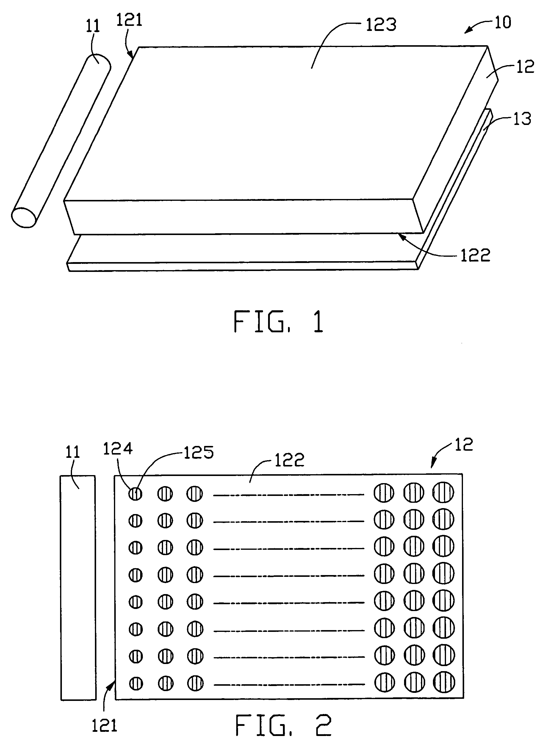
[0023]Referring to FIG. 1, a backlight module 10 according to the present invention is shown. The backlight module 10 comprises a linear light source 11, a transparent light guide plate-like member 12 having a rectangular cross-section, and a reflection plate 13 arranged under the light guide plate 12. The light guide plate 12 comprises a light emitting surface 123, a bottom surface 122 opposite to the light emitting surface 123, and a light incidence surface 121 adjoining both the light emitting surface 123 and the bottom surface 122. The light source 11 is a CCFL (cold cathode fluorescent lamp) disposed adjacent the light incidence surface 121. The reflection plate 13 is disposed under the bottom surface 122.
[0024]Referring to FIG. 2, a plurality of discrete, distinct diffusion elements 124 is arranged in rows and columns at the bottom surface 122 for diffusing light beams. Each diffusion element 124 defines a diffraction grating unit 125 therein. Each diffraction grating unit 125...
second embodiment
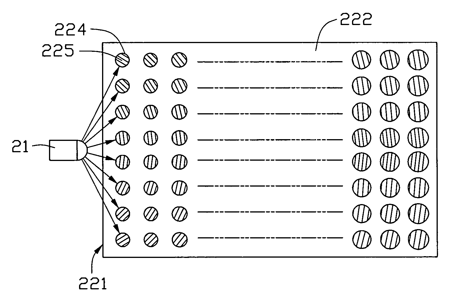
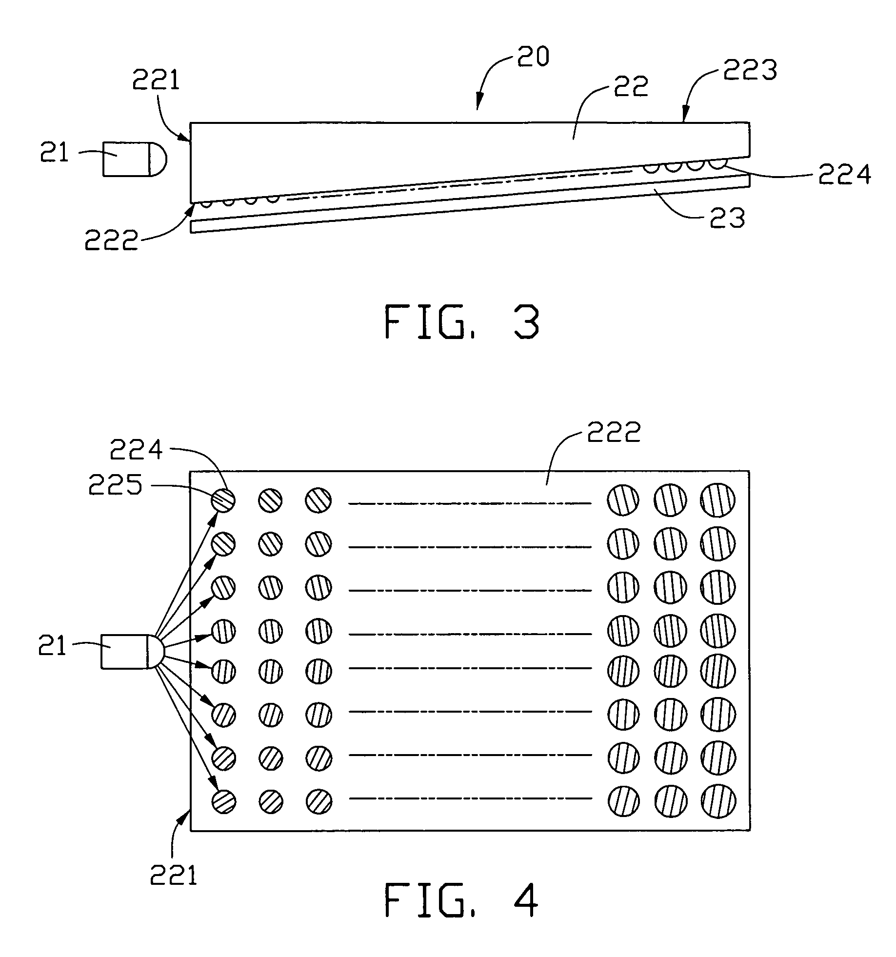
[0027]Referring to FIG. 3, a backlight module 20 according to the present invention is shown. The backlight module 20 comprises a light source 21, a transparent wedgy light guide plate 22, and a reflection plate 23. The light guide plate 22 comprises a light incidence surface 221, a light emitting surface 223, and a bottom surface 222 opposite to the light emitting surface 223. The light source 21 is an LED (light emitting diode), and is disposed adjacent the light incidence surface 221. In alternative embodiments, two or more LEDs can be employed as the light source 21. The reflection plate 23 is disposed under the bottom surface 222. A plurality of diffusion elements 224 is formed on the bottom surface 222, for diffusing light beams.
[0028]Referring to FIG. 4, each diffusion element 224 defines a diffraction grating unit 225 thereon. Grating constants of the diffraction grating units 225 are in the range from 2-5 μm, and preferably 3 μm. Because the light source 21 is an LED, the l...
PUM
 Abstract
Description
Claims
Application Information
 - R&D
- Intellectual Property
- Life Sciences
- Materials
- Tech Scout
- Unparalleled Data Quality
- Higher Quality Content
- 60% Fewer Hallucinations
Browse by: Latest US Patents, China's latest patents, Technical Efficacy Thesaurus, Application Domain, Technology Topic, Popular Technical Reports.
© 2025 PatSnap. All rights reserved.Legal|Privacy policy|Modern Slavery Act Transparency Statement|Sitemap|About US| Contact US: help@patsnap.com


