Eureka AIR delivers breakthrough ideas for toughest innovation challenges, trusted by R&D personnel around the world.

Object tracking using optical correlation and feedback

a technology of applied in the field of object tracking using optical correlation and feedback, can solve the problems of significantly reducing the ability to accurately track motion, requiring relatively high-resolution images, and complex and computationally intensive algorithms

Inactive Publication Date: 2009-04-21
AVAGO TECH INT SALES PTE LTD
View PDF10 Cites 2 Cited by
  • Summary
  • Abstract
  • Description
  • Claims
  • Application Information

AI Technical Summary

Problems solved by technology

However, accurate tracking of motion generally requires fairly high-resolution images as well as sophisticated and computationally intense algorithms.
When images are not recorded at a significantly high resolution and / or computational resources are limited, this can significantly reduce the ability to accurately track motion.

Method used


Image

  • Object tracking using optical correlation and feedback
  • Object tracking using optical correlation and feedback
  • Object tracking using optical correlation and feedback

Examples


Embodiment Construction

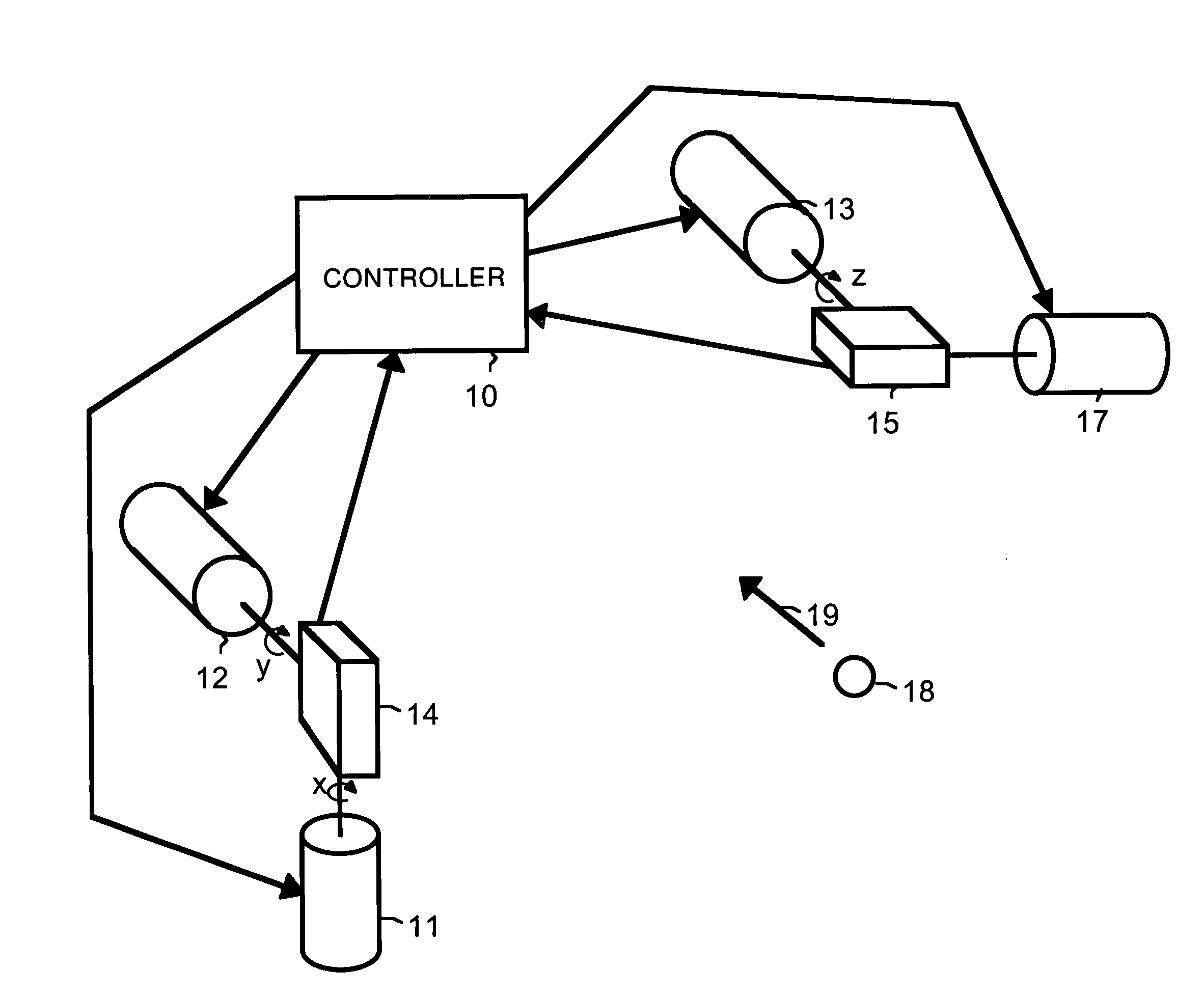
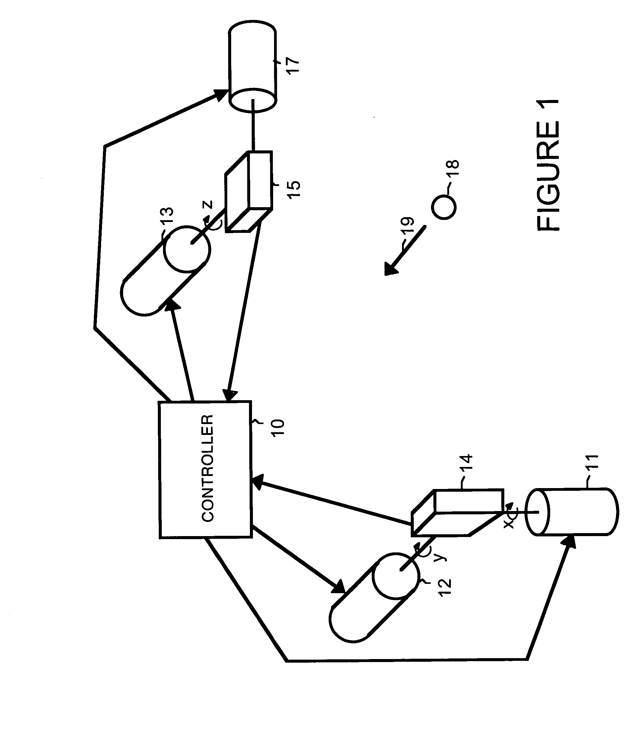
[0005]FIG. 1 shows a system in which an object 18 is tracked using optical correlation and motion feedback. An arrow 19 represents a direction of motion of object 18.

[0006]An optical correlator 14 tracks movement of object 18 in two dimensions, in an x-direction and in a y-direction. In order to do this, optical correlator 14 is rotated by a motor 11 and is rotated by a motor 12 until an image of object 18 is centered within an imager within optical correlator 14. While in the described embodiment of the present invention, the image of the object is centered, in other embodiments, the image of the object can be maintained at locations other than the center of the imager of optical correlator 14.

[0007]Once object 18 is centered within the imager within optical correlator 14, optical correlator 14 detects any movement of object 18 away from the center of the imager within optical correlator 14 in the x-direction and in the y-direction. The amount of detected movement in the x-directio...


PUM


Abstract

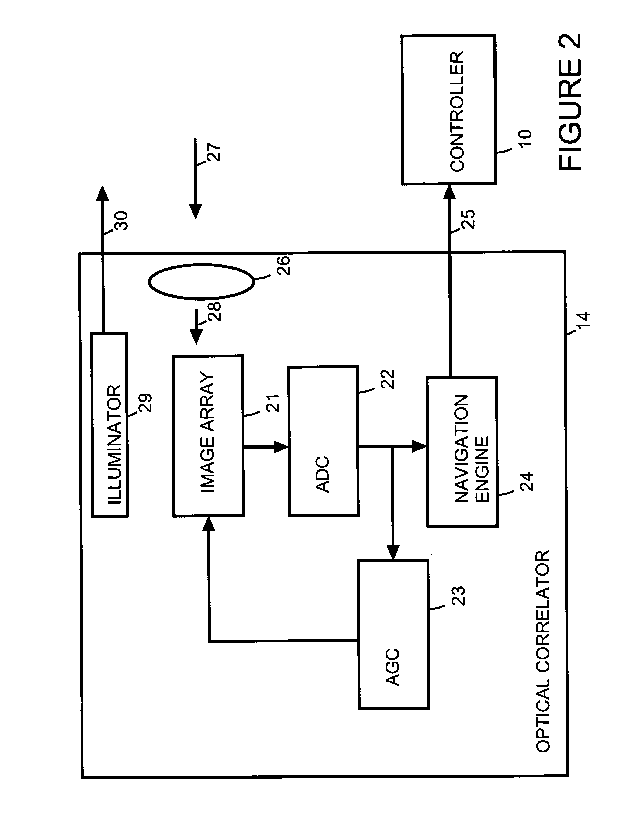
A motion-sensing device is used to track motion of an object. The motion-sensing device includes an optical correlator, a motor system and a controller. The optical correlator has an imager. The optical correlator provides a feedback signal that indicates motion of the object in at least one dimension based on detected movement of an image of the object from a first location within the imager to a second location within the imager. The motor system can move the imager. The controller receives the feedback signal from the optical correlator and uses the feedback signal to calculate motion of the object and to control the motor system to move the imager so that the image of the object is returned to the first location within the imager.

Description

BACKGROUND[0001]Motion of an object can be tracked based on video streams from a stationary camera. However, accurate tracking of motion generally requires fairly high-resolution images as well as sophisticated and computationally intense algorithms. When images are not recorded at a significantly high resolution and / or computational resources are limited, this can significantly reduce the ability to accurately track motion.SUMMARY OF THE DISCLOSURE[0002]In accordance with an embodiment of the present invention, a motion-sensing device is used to track motion of an object. The motion-sensing device includes an optical correlator, a motor system and a controller. The optical correlator has an imager. The optical correlator provides a feedback signal that indicates motion of the object in at least one dimension based on detected movement of an image of the object from a first location within the imager to a second location within the imager. The motor system can move the imager. The c...

Claims


Application Information

Patent Timeline
Patent Type & Authority Patents(United States)
IPC IPC(8): G06K9/00
CPCG06T7/20
Inventor RHEE, QUE-WON
Owner AVAGO TECH INT SALES PTE LTD
Why Eureka
Eureka Blog
Learn More