
Fixed therapeutic oral appliance

a technology for oral appliances and fixed brackets, which is applied in the field of dental appliances, can solve the problems of difficult to adjust the anterior and posterior positions of the appliance, the difficulty of assembling and maintaining the appliance, and the inability to adjust the various vertical settings of the appliance, so as to prolong the longevity of the appliance and allow anterior and posterior adjustmen

Active Publication Date: 2009-04-21
GRP 3 SOLUTIONS L L C
View PDF11 Cites 53 Cited by
  • Summary
  • Abstract
  • Description
  • Claims
  • Application Information

AI Technical Summary

Benefits of technology

[0008]Therefore, it is among the primary objects of the present invention to provide a dental appliance which positions the lower jaw into a forward position and which can increase the vertical opening of the patient's mouth to provide an open airway.
[0010]Still another object of the present invention is to provide a novel dental appliance which will open the patient's airway without interfering with breathing through the mouth and which contains no more than four parts which are readily assembled without the use of screws, wrenches, or special equipment.
[0012]Still a further object resides in providing a dental appliance which allows for various vertical settings, lateral movement for the lower jaw, and which allows anterior and posterior adjustability.
[0013]Another object resides in providing a fixed dental appliance having an insert with adjustment holes surrounded by reinforcement metal film or plates so as to extend longevity of the appliance.

Problems solved by technology

Problems and difficulties have been encountered with such conventional dental appliances which stem largely from the fact that a multiplicity of parts and elements are necessary in order to mount, connect and use the above mentioned assembly.
Such conventional assemblies employ side-bars, clasps, wires and screw mechanisms which are complicated to assemble and require constant maintenance.
Most of the conventional dental appliances do not allow for various vertical settings, nor do they allow for lateral movement for the lower jaw, as well as allowing for anterior and posterior adjustability.

Method used


Image

  • Fixed therapeutic oral appliance
  • Fixed therapeutic oral appliance

Examples


Embodiment Construction

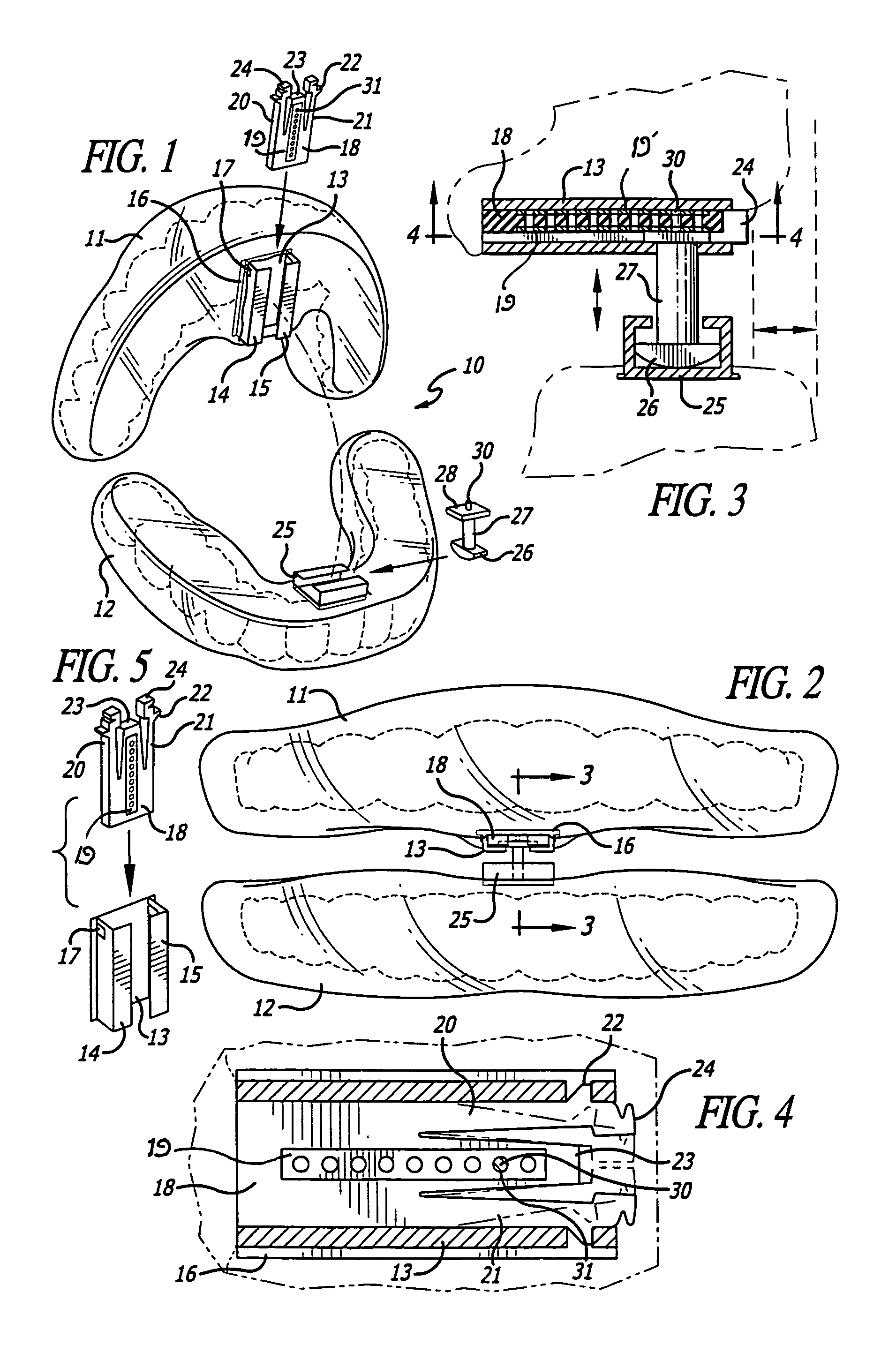
[0020]Referring to FIG. 1, the novel fixed dental appliance incorporating the present invention is illustrated in the general direction of arrow 10 which includes an upper and a lower thermoplastic transparent form or member indicated by numerals 11 and 12 respectively. These forms are processed by a laboratory technician so that the members or forms will fit both oral arches when worn by the user. The upper form 11 includes a bite block taking the form of an elongated channel element 13 having a slot defined between the opposing edges of flanges 14 and 15 respectively. The channel includes a base element 16 that is embedded in the thermoplastic material of the form 11. Also, each side of the channel element 13 includes an opening, such as opening 17. The opposite ends of the channel element are open so as to insertably receive an insert 18 which includes a linear line of holes 31 and a pair of flexible arms 20 and 21 on opposite sides and having distal ends which reside on the ante...


PUM


Abstract

An oral appliance having upper and lower channel elements attached, respectively, to upper and lower bite blocks. The two channel elements are oriented at a right angle with respect to each other. One of the channel elements carries a removable insert having an array of adjustment holes. A removable coupling member has a support rod with an anchor piece and anchor pin at one of its ends. The anchor piece is received by the channel element carrying the insert, while the anchor pin is received by one of the insert's adjustment holes. A base at the other end of the support rod is received by the other channel element, so that the coupling member may releasably connect the two channel elements together.

Description

Priority Claimed on Ser. No. 60 / 568,163 filed May 6, 2004 PENDINGBACKGROUND OF THE INVENTION[0001]1. Field of the Invention[0002]The present invention relates to the field of dental appliances, and more particularly to a sleep apnea appliance for adjustably positioning the user's lower jaw into a forward position and for increasing the vertical dimensions of the user's mouth for opening the user's airway for easier breathing.[0003]2. Brief Description of the Prior Art[0004]In the past, it has been the conventional practice to provide a dental appliance to be worn by a user at night for treatment of snoring and obstructive sleep apnea. The appliance generally consists of an upper bite block conforming to the user's maxillary dentition, a lower bite block conforming to the user's mandibular dentition, and a connecting assembly secured to an anterior region of the upper and lower bite blocks for adjustably coupling the upper and lower bite blocks together.[0005]Problems and difficultie...

Claims


Application Information

Patent Timeline
Patent Type & Authority Patents(United States)
IPC IPC(8): A61C5/14A61C19/04A61C3/00
CPCA61F5/566Y10S602/902
Inventor NAHABEDIAN, LIONEL
Owner GRP 3 SOLUTIONS L L C
Learn More