
Method and device for local spectral analysis of an ultrasonic signal

a local spectral analysis and ultrasonic signal technology, applied in the direction of analyzing solids using sonic/ultrasonic/infrasonic waves, using reradiation, processing detected response signals, etc., can solve the problems of inability to obtain reliable diagnosis, extremely complex signals, limited conventional methods, etc., to achieve greater and more precise information on the structure under examination

Inactive Publication Date: 2009-03-31
ACTIS ACTIVE SENSORS +1
View PDF22 Cites 12 Cited by
  • Summary
  • Abstract
  • Description
  • Claims
  • Application Information

AI Technical Summary

Benefits of technology

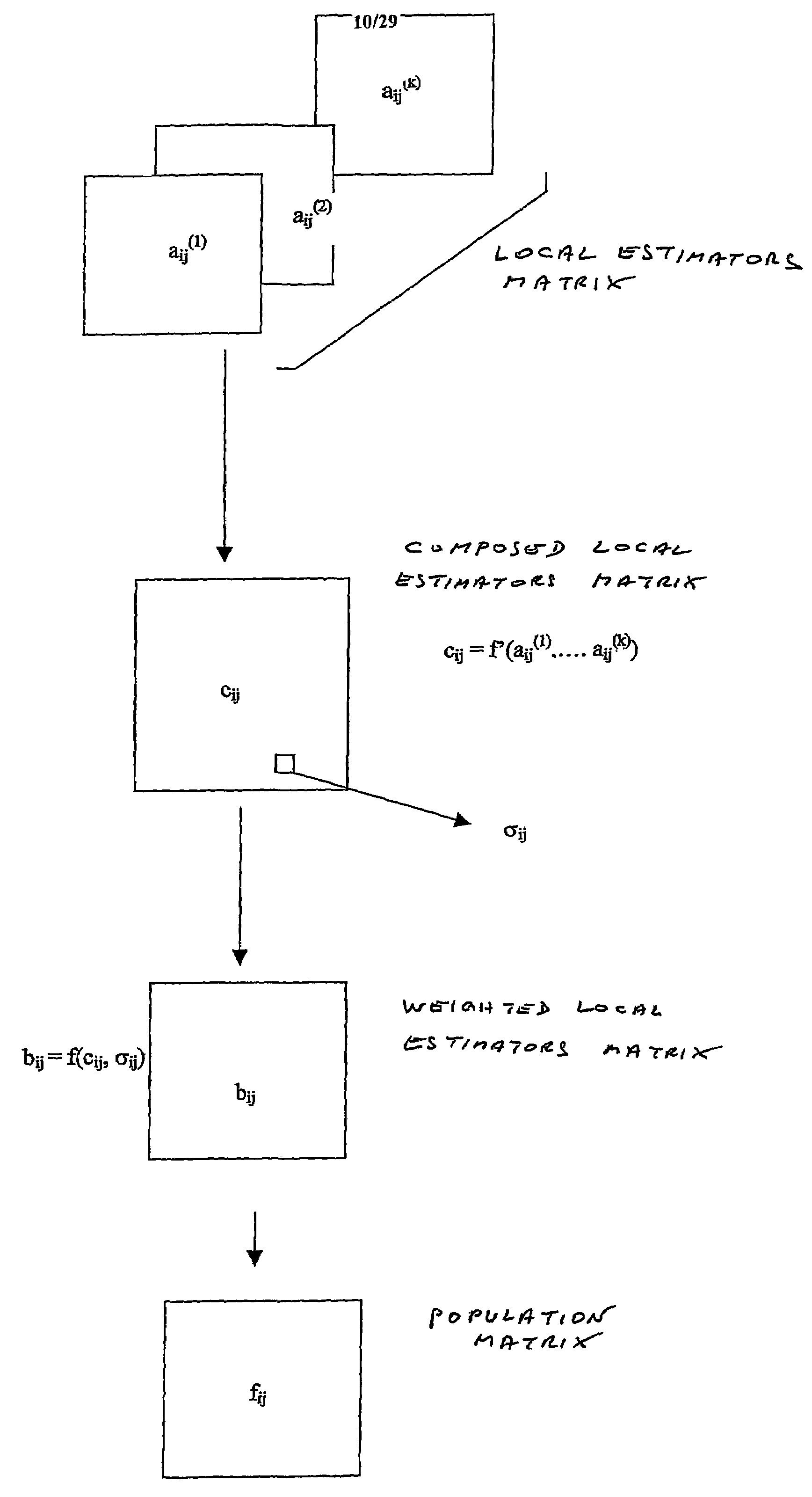
The present invention provides an improvement and extension of the method described in EP-A-0.341.003 for analyzing the structure of a sample using spectral analysis. The invention allows for better and more precise information to be obtained by using a combination of local estimators and the shape parameters of their distribution histograms. The method can also be extended by using different mother wavelets, decomposing the spectral band into sub-bands, and using different levels of decomposition. The combination of local estimators can also be used as a combined local estimator by combining the coefficients of different degrees of the interpolating polynomial. Overall, the invention provides greater and more accurate information on the structure of a sample.

Problems solved by technology

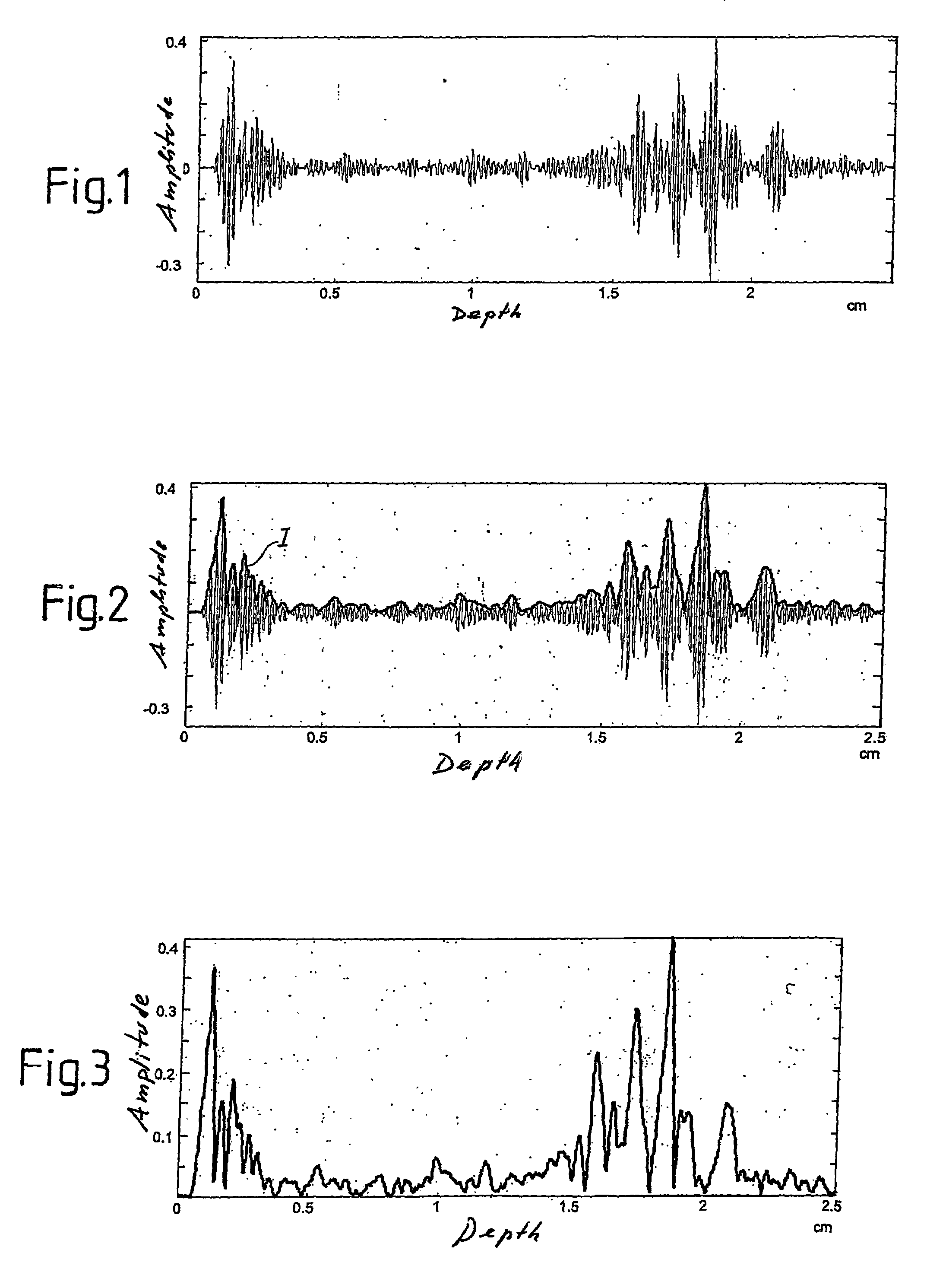
The back-propagated acoustic signal consists of the temporal overlapping of the contributions from each reflector and / or diffuser; the result is a signal having an extremely complex shape, due to the random nature of the distribution and the shapes and mechanical properties of the diffusers and reflectors.
Consequently there are situations in which the conventional methods are found to be limited since, owing to low sensitivity or low specificity, it is not possible to obtain a reliable diagnosis of pathology.
In practice, the ultrasonic signals backscattered from the microstructures, due to the differences in the propagation path, interfere on the face of the receiving transducer in a destructive or constructive way, resulting in the “speckle” effect in the images.
However, the methods developed up to the present time have not proved to be effective, either because they are unsuitable to characterize tissue reliably, or because of the excessive computing capacity required for the algorithms used, which cannot be implemented in a way that permits real time display of the results and would therefore not allow clinical applications where the speed of data output is a basic requirement.

Method used


Image

  • Method and device for local spectral analysis of an ultrasonic signal
  • Method and device for local spectral analysis of an ultrasonic signal
  • Method and device for local spectral analysis of an ultrasonic signal

Examples


Embodiment Construction

[0081]FIG. 5 shows a highly schematic block diagram of an ultrasound scanning apparatus. The number 1 indicates a transducer of the scanning head, indicated generically with 2, which emits the ultrasonic excitation signal and receives the ultrasonic response signal. The analog output 3 of the scanning head is connected to an acquisition card 5. The latter produces a sampled and digitized radio frequency signal, which forms the input for a bank of integrated FIR filters, indicated generically with 7. The bank of filters 7 can consist of any commercially available integrated device, for example the 43168 circuit produced by Harris, the GF191 circuit produced by Gennum, the GEC 16256 circuit produced by Plessey, or the GC2011 circuit produced by Graychip. The FIR filter 7 is associated with a digital signal processor (DSP) indicated with 9, which acts as a controller for the whole processing unit. The microcontroller 9 can be, for example, a TMS 32031 DSP produced by Texas (USA) or ano...


PUM

PropertyMeasurementUnit
frequencyaaaaaaaaaa
frequencyaaaaaaaaaa
frequencyaaaaaaaaaa

Abstract

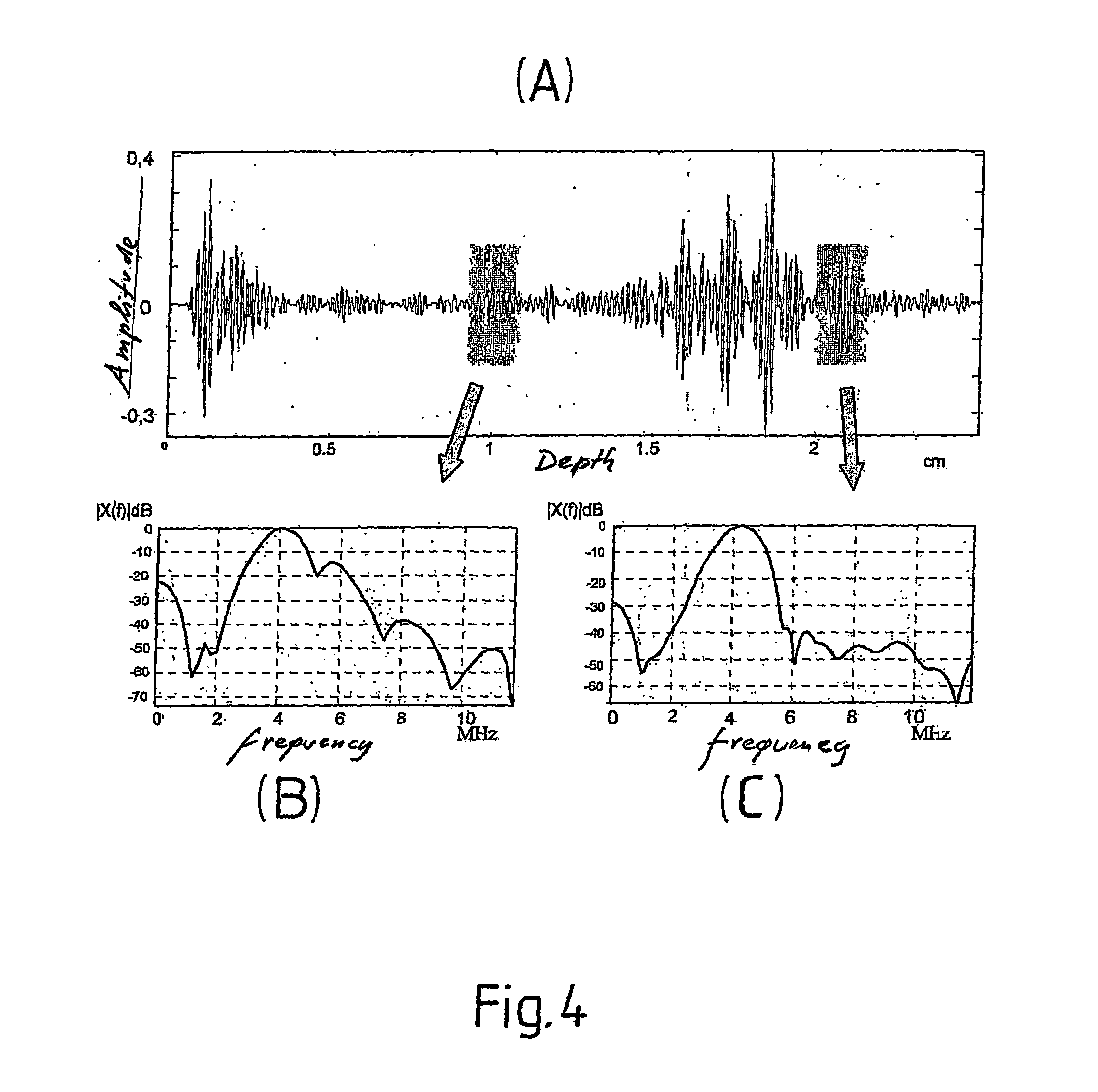
The method decomposes the radio frequency signal into sub-bands by filtering, for example with a time-frequency transform. From the coefficients acquired through decomposition a matrix of spectral coefficients is obtained, from which local estimators are obtained, constituted in particular by the coefficients of the interpolating polynomials. The statistical distribution of the local estimators is evaluated in windows overlaid on the ultrasound frame. The conformation of the distribution histograms of the spectral coefficients provides a parameter which, combined with the local estimators, provides weighted local estimators, which contain spectral information useful in the identification of specific structures in the organ subjected to ultrasound analysis.

Description

TECHNICAL FIELD[0001]The present invention relates to a method to process ultrasonic signals, especially in the field of non-invasive clinical tests based on the ultrasonic method. The invention also relates to an ultrasound device for the implementation of a processing method of the ultrasonic signals.STATE OF THE ART[0002]Ultrasound scanning is a non-invasive investigation method for examining internal organs of the human and animal body and also for non-invasive examination of other types of structures, including non-living and inorganic structures. As is known, it is based on the production of a series of ultrasonic signals (forming an acoustic beam) which are directed into the body and which excite an ultrasonic response signal, caused by the back reflection and / or scattering of sound waves by the diffusers and / or reflectors present within the region under observation. The probe for patient'transmitting and receiving the ultrasonic signal sends the response signal to a receivin...

Claims


Application Information

Patent Timeline
Patent Type & Authority Patents(United States)
IPC IPC(8): G01N29/46A61B8/00G06K9/20G01S7/52G01S15/89
CPCG01S7/52036G01S15/8977
Inventor MASOTTI, LEONARDOBIAGI, ELENAGRANCHI, SIMONABRESCHI, LUCA
Owner ACTIS ACTIVE SENSORS
Learn More