
Vehicle periphery viewing apparatus

a viewing apparatus and periphery technology, applied in the field of vehicle periphery viewing apparatus, can solve the problems of not always easy for the viewer to recognize surrounding images, and cannot correctly represent an object having a height, and achieve the effects of easy processing, simplified internal configuration and software programs, and long service li

Inactive Publication Date: 2009-03-17
AUTONETWORKS TECH LTD +2
View PDF14 Cites 101 Cited by
  • Summary
  • Abstract
  • Description
  • Claims
  • Application Information

AI Technical Summary

Benefits of technology

[0011]From this point of view, as shown in FIG. 10, the image of the plan view coordinate obtained by the view point conversion has an advantage of an easy grasp of the distance between a peripheral obstacle and a vehicle.
[0037]By thus configuration, the image processing device performs an image synthesis for the long distance image after enlarging or reducing the long distance image without changing the long distance image included in the original image. Therefore, the long distance image can be easily processed, and thus, simplification of internal configuration and software programs within the image processing device, as well as efficient image processing of the long distance image, can be achieved.

Problems solved by technology

With the original image at the point of view from which the object is obliquely seen downward, as shown in FIG. 8, since the installation height of the back camera 1 is typically different from the view height of a viewer, it is not always easy for the viewer to recognize surrounding images.
However, the view point conversion technique using the geometrical correction is performed based on a plane in parallel to the ground, and therefore, cannot correctly represent an object having a height.

Method used


Image

  • Vehicle periphery viewing apparatus
  • Vehicle periphery viewing apparatus
  • Vehicle periphery viewing apparatus

Examples


Embodiment Construction

[0051]

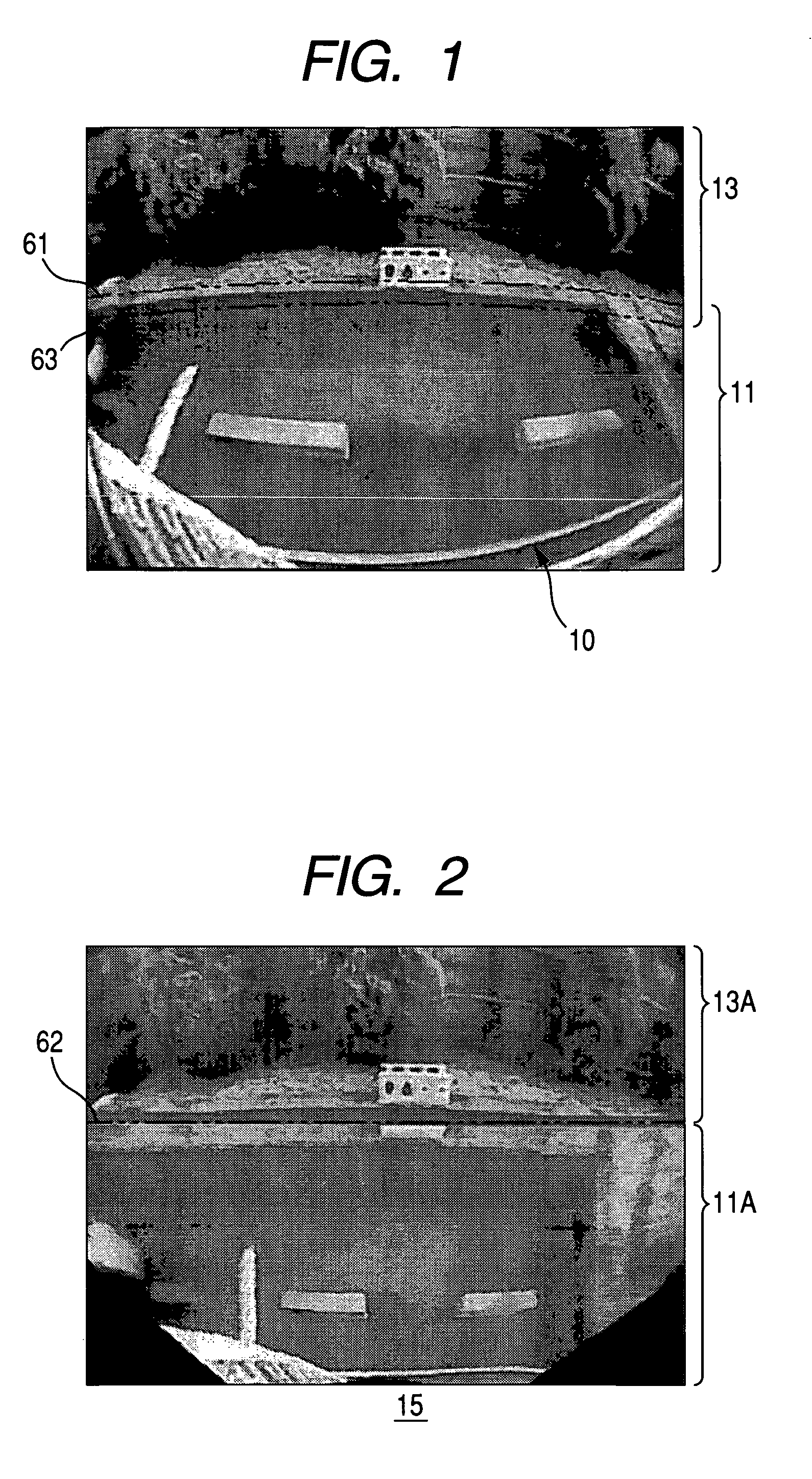
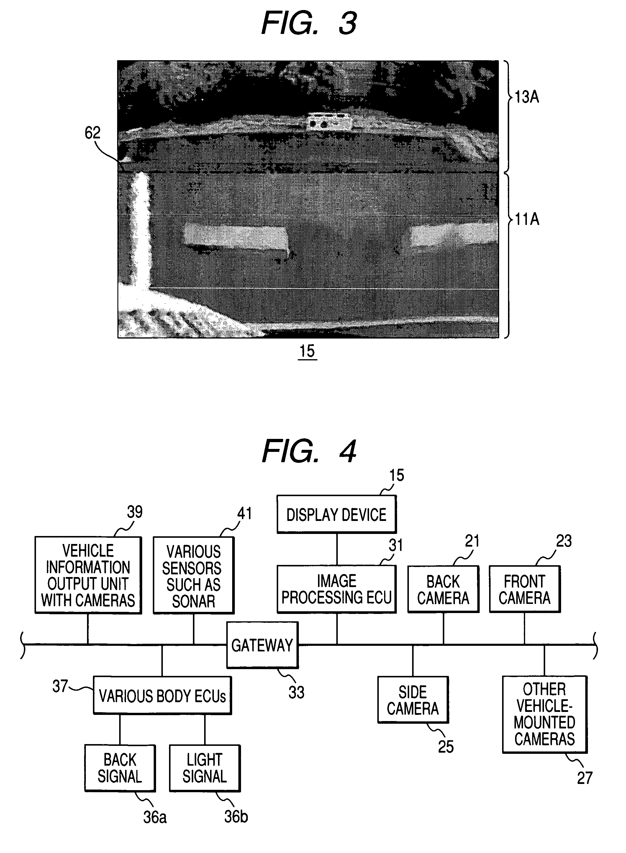
[0052]FIG. 1 is a view showing an example of an original image captured by a camera of a vehicle periphery viewing apparatus according to an embodiment of the present invention, FIGS. 2 and 3 are views showing an example of a display in the vehicle periphery viewing apparatus according to the embodiment of the present invention. In this embodiment, elements having the same function as the conventional vehicle periphery viewing apparatus shown in FIG. 9 are denoted by the same reference numerals.

[0053]In order for a driver (user) in a vehicle to ascertain peripheral safety, the vehicle periphery viewing apparatus photographs an original image 10 for periphery including an area behind the vehicle, as shown in FIG. 1, at a point of view from which an object is obliquely seen downward as shown in FIG. 9. The vehicle periphery viewing apparatus sets an image 11 within a short distance range (hereinafter, referred to as a ‘short distance image’) corresponding to a lower portion of t...


PUM


Abstract

A vehicle periphery viewing apparatus for capturing a vehicle-peripheral image includes: an image capturing device disposed on predetermined position; a display device disposed within the vehicle; and an image processing device performing an image division of the original image into a first image and a second image. The image capturing device captures an original image from the predetermined position. The display device displays the captured vehicle-peripheral image. The image processing device performs a coordinate conversion into a plan view coordinate by using a geometrical correction for the first image. The image processing device performs a predetermined image synthesis for the first image and the second image. The image processing device displays a synthesized image on the display device.

Description

BACKGROUND OF THE INVENTION[0001]1. Field of the Invention[0002]The present invention relates to a vehicle periphery viewing apparatus for capturing images in the periphery of a vehicle with an image capturing device and displaying the sensed images on a display device in the vehicle.[0003]2. Description of the Related Art[0004]In the field of vehicles, for example, in order to facilitate a driver to see an area behind a vehicle, the area is captured by a back camera installed in the rear of the vehicle and the captured area is displayed on a display device such as a liquid crystal panel installed in the vehicle.[0005]Requirements for such a back camera can include the following two points.[0006](1) Seeing walkers, obstacles and so on in the periphery of a vehicle using a camera image.[0007](2) Grasping the sense of distance between a vehicle and another vehicle or an obstacle such as a wall with a resolution of 10 cm, for example, when the vehicle reverses.[0008]Of both points, poi...

Claims


Application Information

Patent Timeline
Patent Type & Authority Patents(United States)
IPC IPC(8): G09G5/00B60R21/00B60R1/00B60R1/02G01C21/26G01C21/30G06K9/00G06T1/00G06T3/00G06T5/00G08G1/16H04N7/18
CPCB60R1/00G06T5/006B60R2300/105B60R2300/30B60R2300/60B60R2300/8066
Inventor YOSHIMURA, AKINOBU
Owner AUTONETWORKS TECH LTD
Learn More